
RX7 2RTR- 1308cc 1.3L FI (1987)
Fuel Pump Relay: Testing and Inspection
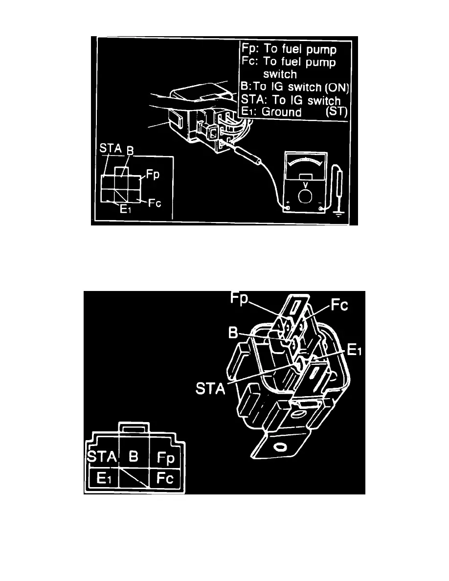
Fig. 83 Circuit opening relay connector rear side terminal identification.
1.
Check voltage between each terminal and ground, Fig. 83.
2.
There should be zero volts at terminal Fp with ignition switch in On position and 12 volts in all other conditions, 12 volts at terminal Fc with
ignition switch in On position and zero volt in all other conditions, 12 volts at terminal B at all times, 12 volts at terminal STA with ignition switch
at ST position and zero volts in all other conditions and zero volts at terminal E1 at all times.
Fig. 84 Circuit opening relay connector front side terminal identification.
3.
If voltages are not as described, check resistance between terminals, Fig. 84, as follows:
a. Resistance between terminals STA and E1 should be 15-30 ohms.
b. Resistance between terminals B and Fc should be 80-150 ohms.
c. Resistance between terminals B and Fp should be infinite.
4.
If resistance is not as described, replace circuit opening relay.