
Tribute 2WD L4-2.3L (2005)
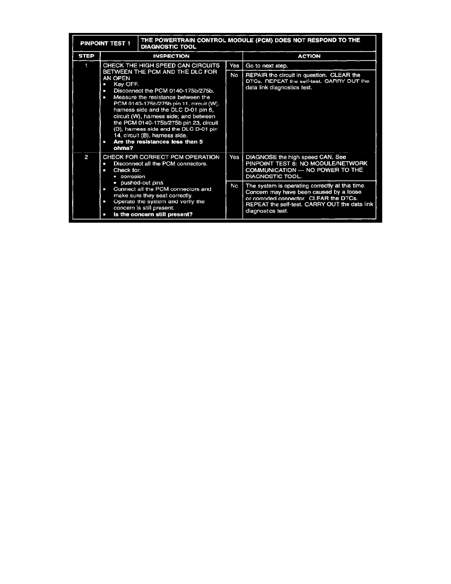
PINPOINT TEST 1: THE POWERTRAIN CONTROL MODULE (PCM) DOES NOT RESPOND TO THE DIAGNOSTIC TOOL
Step 1 - 2
Normal Operation
The PCM communicates with the diagnostic tool through the high speed CAN communications network circuits (W) and (B). If one of the bus wires
becomes shorted to ground or voltage, communications can continue at a reduced level. The PCM and instrument cluster share network termination
responsibilities with the use of a split termination resistor in each module. If either of these termination resistors is lost, network communications will not
be possible. Check circuits (W) and (B) between the PCM 0140-175b and the data link connector (DLC) D-01. Total resistance values must not be more
than 5 Ohms. If the resistance is more than 5 Ohms there is an open in one of the high speed CAN circuits, damage to the DLC D-01, damage to the
PCM 0140-175b, or a problem in an in-line connector.
Possible Causes
-
high speed CAN circuits (W) and (B) shorted to ground or open
-
DLC D-01
-
PCM 0140-175b
-
instrument cluster
-
PCM
-
PCM or instrument cluster termination resistors
Pinpoint Test 2
PINPOINT TEST 2: THE RESTRAINT CONTROL MODULE (RCM) DOES NOT RESPOND TO THE DIAGNOSTIC TOOL