
Tribute 2WD L4-2.3L (2005)
Engine Control Module: Testing and Inspection
POWERTRAIN CONTROL MODULE (PCM) INSPECTION
CAUTION: The PCM terminal voltages vary with change in measuring conditions and vehicle conditions. Always carry out a complete inspection of
the input systems, output systems, and PCM to determine the cause of the concern. Otherwise, an incorrect diagnosis may occur.
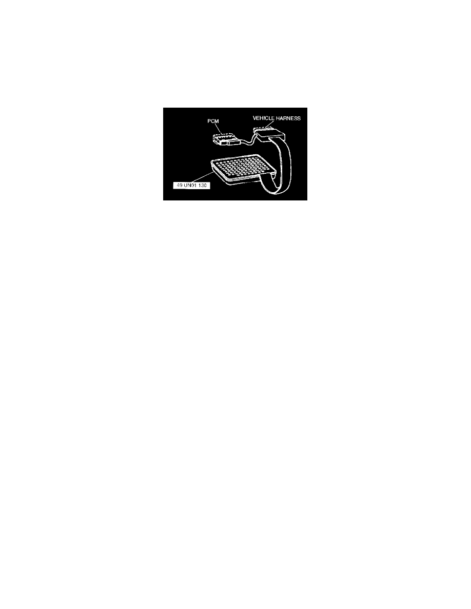
Using SST (150 Pin Breakout Box)
1. Disconnect the negative battery cable.
2. Disconnect the PCM connector.
3. Connect the SST (150 Pin Breakout Box) to the PCM as shown.
4. Tighten the connector bolt.
Tightening torque 7.9 - 10.7 N.m (80 - 110 kgf.m, 69.5 - 95.4 In.lbf)
5. Connect the negative battery cable
6. Measure the voltage at each terminal.
7. If any incorrect voltage is detected, check related systems, wiring harnesses and connectors referring to the possible malfunction in the terminal
voltage list.