
Tribute 2WD L4-2.3L (2005)
19. Attach the restraint system diagnostic tool to the vehicle harness side of the driver-side safety canopy module electrical connector.
All vehicles
20. Install the RCM fuse 33 (15 A) to the SJB.
21. Repower the system. See SUPPLEMENTAL RESTRAINT SYSTEM (SRS) DEPOWERING AND REPOWERING.
Reactivation
All vehicles
1. Depower the system. See SUPPLEMENTAL RESTRAINT SYSTEM (SRS) DEPOWERING AND REPOWERING.
Vehicle with safety canopy
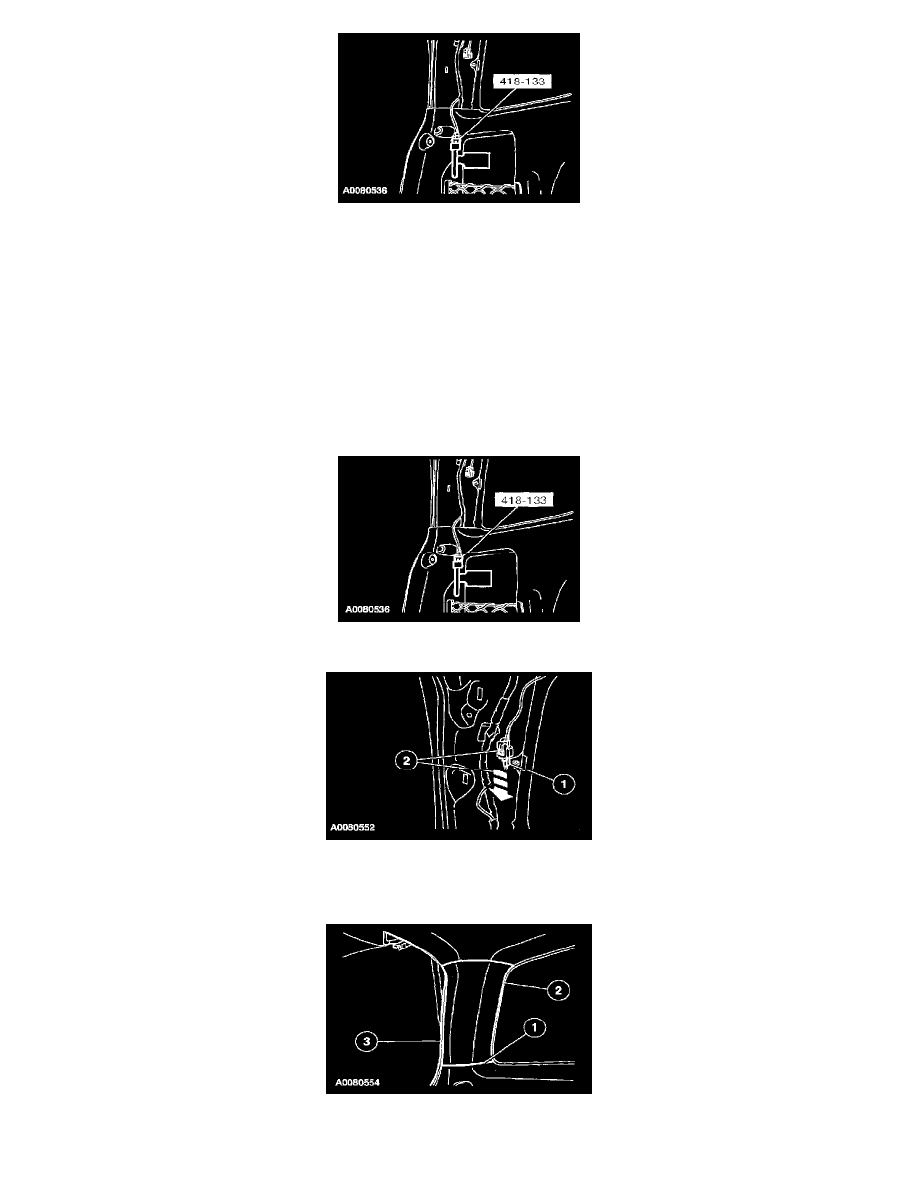
2. Remove the restraint system diagnostic tool from the vehicle harness side of the driver-side safety canopy module electrical connector.
3. Connect the driver-side safety canopy module electrical connector.
1. Connect the driver-side safety canopy module electrical connector.
2. Slide and engage the driver-side safety canopy module electrical connector locking clip.
4. Install the driver-side D-pillar trim panel.
1. Engage the D-pillar trim panel to the quarter trim panel.