Tribute 4WD L4-2.5L Hybrid (2009)

WARNING:If a vehicle has been in a crash, inspect the restraints control module (RCM) and the impact sensor (if equipped) mounting areas for
deformation. If damaged, restore the mounting areas to the original production configuration. A new RCM and sensors must be installed whether or not
the air bags have deployed. Failure to follow these instructions may result in serious personal injury or death in a crash.
WARNING:To reduce the risk of accidental deployment, do not use any memory saver devices. Failure to follow this instruction may result in serious
personal injury or death.
NOTE:The air bag warning lamp illuminates when the restraints control module (RCM) fuse is removed and the ignition switch is ON. This is normal
operation and does not indicate a supplemental restraint system (SRS) fault.
NOTE:The SRS must be fully operational and free of faults before releasing the vehicle to the customer.
NOTE:Repair is made by installing a new part only. If the new part does not correct the condition, install the original part and carry out the diagnostic
procedure again.
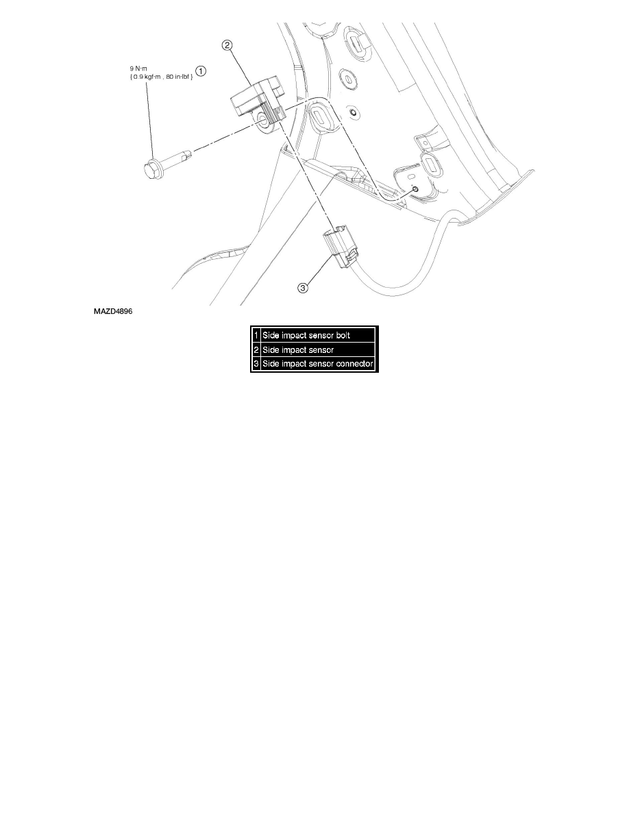
NOTE:RH side shown, LH side similar.
1. Depower the system. See See: Body and Frame/Interior Moulding / Trim/Dashboard / Instrument Panel/Air Bag(s) Arming and
Disarming/Service and Repair/Supplemental Restraint System (SRS) Depowering And Repowering.
2. Remove the C-pillar trim panel. See See: Body and Frame/Interior Moulding / Trim/Trim Panel/Service and Repair/C-Pillar Trim Panel
Removal/Installation.
3. Remove the side impact sensor bolt.
-
Tighten to 9 Nm {0.9 kgf-m, 80 in-lbf}.
WARNING:Always tighten the fasteners of the restraints control module (RCM) and impact sensor (if equipped) to the specified torque. Failure to do
so may result in incorrect restraint system operation, which increases the risk of personal injury or death in a crash.
NOTE:Make sure the C-pillar and side impact sensor mating surfaces are clean and free of foreign material.
NOTE:Note position of the locator tab on the front impact severity sensor for installation.
4. Disconnect the electrical connector and remove the side impact sensor.
5. To install, reverse the removal procedure.
6. Repower the system. See See: Body and Frame/Interior Moulding / Trim/Dashboard / Instrument Panel/Air Bag(s) Arming and Disarming/Service
and Repair/Supplemental Restraint System (SRS) Depowering And Repowering.
