
Sable V6-183 3.0L DOHC VIN S MFI (1997)
Load Compensator: Adjustments
SET UP
1. Drive vehicle onto a hoist or alignment machine, so that vehicle is level and wheels are on a flat surface. Don't Frame lift.
2. Make sure fuel level is at least 3/4 full.
ADJUSTMENT
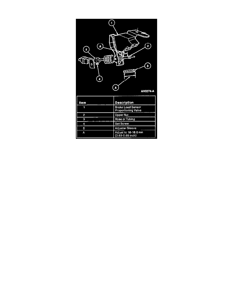
NOTE:Do not change position of the upper nut on valve operating rod.
3. Loosen valve adjuster setscrew.
4. Obtain a piece of rubber or vacuum hose or plastic tubing 3/8-inch OD x 1/4-inch ID. Cut a piece 16.3 mm ± 0.3 mm (0.64 ± 0.012") and slice it
lengthwise as shown.
5. Place hose or tubing on valve operating rod.
6. Make sure the adjuster sleeve is resting on the lower mounting bracket and not corroded to the rod. It must move freely when the set screw is
loosened. Tighten setscrew. The dimension will position the valve for normal operation. Remove hose or tube.
ALTERNATE ADJUSTMENT/CHECK METHOD:
-
Set an inside vernier caliper to 16.3 mm (0.64 inch) and insert between the nut and grommet.
-
Perform adjustment as above. If further adjustment is necessary refer to the following procedure:
^
To decrease pressure at rear brakes install setscrew in adjuster sleeve in desired position.