
Sable V6-183 3.0L DOHC VIN S MFI (1997)
Connecting Rod: Testing and Inspection
Inspection
INSPECTION
1. The connecting rod should be carefully inspected for conformance to specifications. Various forms of engine wear can be readily identified as
follows:
-
A shiny surface on the pin boss side of the piston (6108) or a sideways wear pattern on the entire piston skirt usually indicates that a
connecting rod is bent or a piston pin hole is not in proper relation to the piston skirt and ring grooves.
-
Abnormal connecting rod bearing wear can be caused by either a bent connecting rod, an improperly machined journal, or a tapered
connecting rod bore.
-
Twisted connecting rods will not create an easily identifiable wear pattern. Badly twisted connecting rods will disturb the entire action of the
piston, pin and piston ring, and connecting rod assembly and may be the cause of excessive oil consumption.
CAUTION: Do not ream or hone the pin bore in the connecting rod. Replace damaged connecting rod nuts and bolts or engine damage may
occur.
2. Check the inner diameter of the connecting rod piston pin bore. If the pin bore in the connecting rod is larger than specification, install a 0.03 mm
(0.0012-inch) oversize piston pin (6135). Refer to Piston Pin Fit for testing procedures. See: Piston Pin Fit
3. Replace any damaged connecting rod nuts and bolts.
FRACTURES AND OUT-OF-ROUND
Inspect the connecting rods for signs of fractures and the bearing bores for out-of-round and taper. If the bore exceeds the recommended limits
and/or if the connecting rod is fractured, it should be replaced.
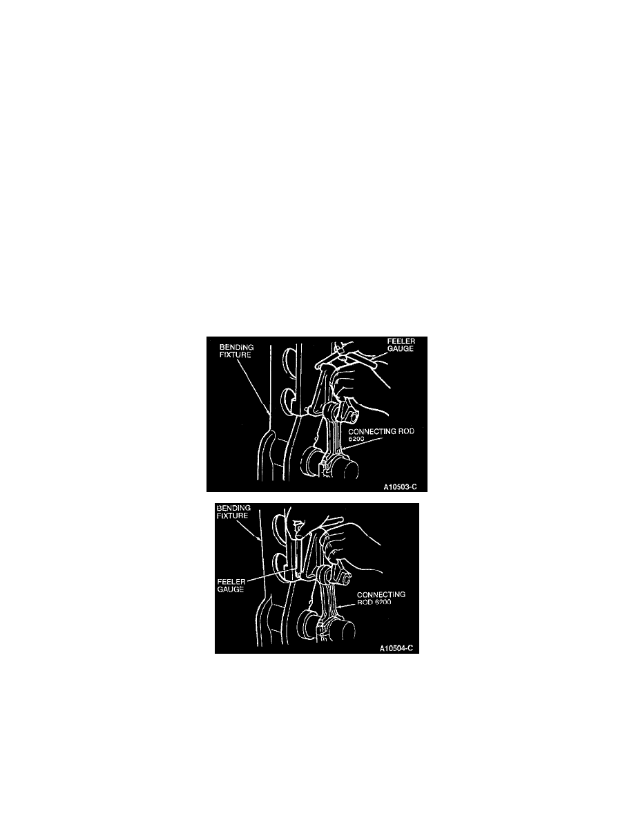
BEND OR TWIST CHECK
-
Check the connecting rod for bends or twists on a suitable alignment fixture. Follow the manufacturer's instructions for the specific alignment
fixture being used. If the bend and/or twist exceeds the specifications, the connecting rod must be replaced.
-
Use a bending fixture and a feeler gauge to inspect the connecting rod bending clearance.
-
The bend limit is 0.038 mm per 25 mm (0.0015 inch per inch).
-
The twist limit is 0.050 mm per 25 mm (0.0020 inch per inch).