
Sable V6-183 3.0L DOHC VIN S MFI (1997)
Valve Guide: Testing and Inspection
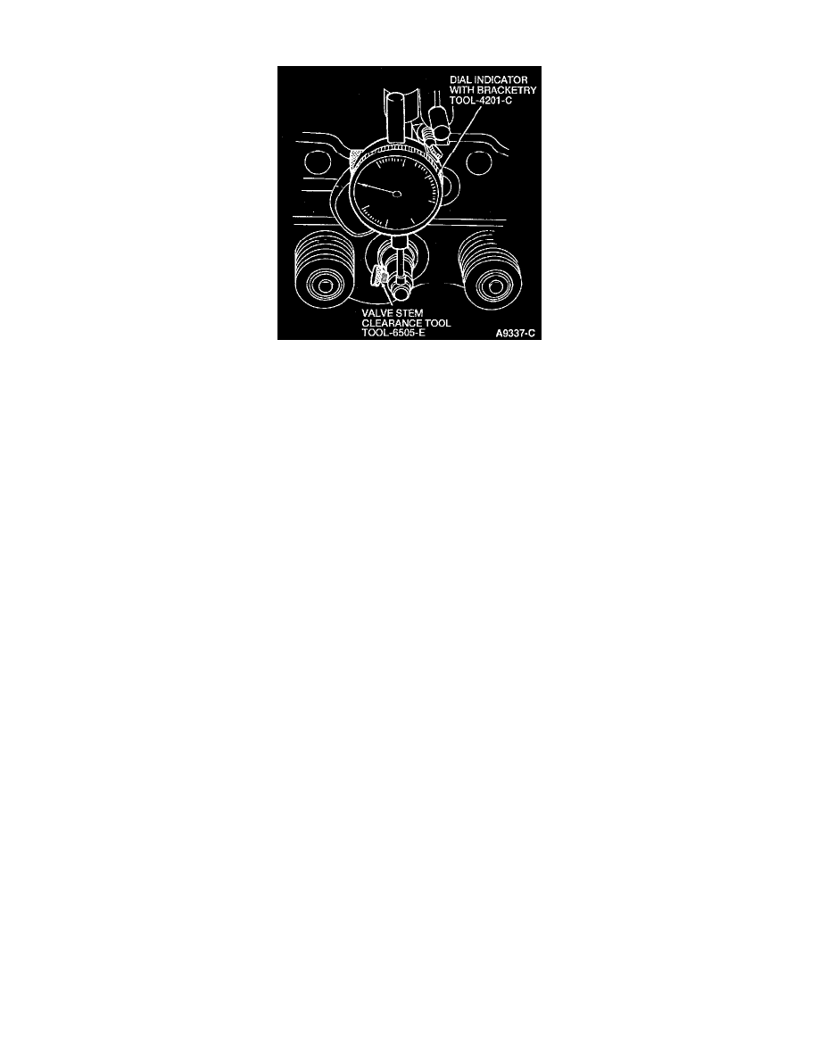
DESCRIPTION
Check the valve stem-to-valve guide clearance of each valve in its respective valve guide with Valve Stem Clearance Tool TOOL-6505-E and Dial
Indicator with Bracketry TOOL-4201-C or equivalent. Use a flat-end indicator point.
PROCEDURES
1. Install the tool on the valve stem until the lip is fully seated, and tighten the knurled set screw firmly.
2. Permit the valve to drop away from its seat until the tool contacts the upper surface of the valve guide.
3. Position and zero the dial indicator on the cylinder head.
4. Move the valve back and forth 90° from the dial indicator shaft.
5. Divide the measurement by two to determine the actual guide clearance.
-
The intake clearance is 0.020-0.069 mm (0.0007-0.027 inch).
-
The exhaust clearance is 0.045-0.094 mm (0.0017-0.037 inch).
NOTE: The service clearance is intended as an aid to diagnose engine noise only and does not constitute a failure or indicate need for service.
However, when overhauling or reconditioning a cylinder head, the service clearance should be regarded as having a practical working value and
used as an aid when installing the valve guide and/or valve to ensure extended service life.
6. If the valve stem-to-valve guide clearance exceeds the service clearance, replace the valve and/or guide valve. Always reface the valve seat after
the valve and/or valve guide has been replaced.
7. If the valve and/or valve seat has been refaced, it will be necessary to check the clearance between the rocker arm bearing surface or valve tappet
surface (depending upon application) and base circle of the camshaft lobe with the valve train installed in the engine.