
3000GT V6-3.0L SOHC (1998)
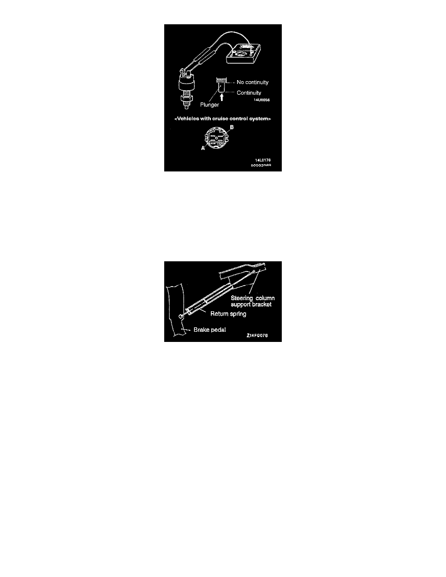
1) Connect a circuit tester to the stop light switch.
2) The stop light switch is in good condition if there is no continuity when the plunger is pushed in to a depth of within 4 mm (0.16 inch) from the
outer case edge surface, and if there is continuity when it is released. For vehicles with the cruise control system, the check for continuity should
be made at connectors "a" and "b" of the stop light switch.
INSTALLATION
Installation in reverse order as removal.
Installation Service Point
>A< Return Spring Installation.
Install the return spring with the shorter hook in the brake pedal.
Post-installation Operation:
-
Steering Column Assembly Installation.
-
Clutch Pedal Adjustment.