
3000GT V6-3.0L SOHC (1998)
CAUTION: The speed sensor pole piece is magnetized by a bulletin magnet inside the sensor, so it tends to attract metal. If the pole piece is
damaged, accurate wheel speed detection may not be expected.
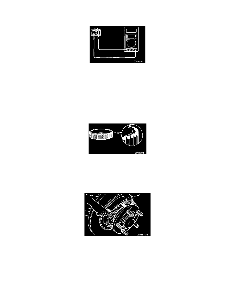
2) Measure resistance between speed sensor terminals.
Standard value:
Front 1.44 - 1.76 k ohms.
Rear 1.0 - 1.3 k ohms.
If the internal resistance of the speed sensor is out of specification, replace with a new one.
3) Check the speed sensor cable for open circuit and replace if faulty.
NOTE: Remove the cable clamp from the body and, while flexing the cable near the clamp, check for temporary open circuit. Also check
connector connection and terminal insertion.
Toothed ABS Rotor Check
Check whether the ABS rotor teeth are broken or deformed. Replace the ABS rotor if the teeth are damaged or deformed.
INSTALLATION
Installation in reverse order as removal.
Installation Service Points
>A< Rear Speed Sensor Installation.
Insert a feeler gauge between the speed sensor pole piece and the ABS rotor tooth surface and tighten the speed sensor to specified torque where
the clearance is as specified all around.
Standard value: 0.2 - 0.7 mm (0.008 - 0.028 inch)