
3000GT V6-3.0L SOHC (1998)
Crankshaft Position Sensor: Testing and Inspection
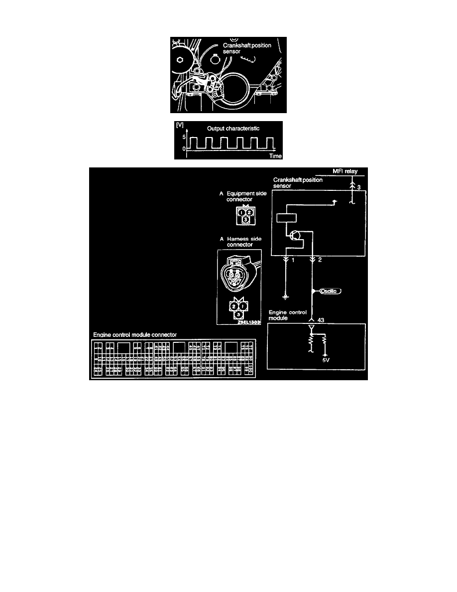
OPERATION
-
The crankshaft position sensor senses the crank angle (piston position) of each cylinder; converts it into a pulse signal and inputs it to the engine
control module, which then controls the engine speed and controls the fuel injection timing and ignition timing based on the input signal.
-
Power to the crankshaft position sensor is supplied from the MFI relay and is grounded to the body. The crankshaft position sensor generates a
pulse signal as it repeatedly connects and disconnects between 5 V voltage supplied from the engine control module and ground.
TROUBLESHOOTING HINTS
Hint 1: If unexpected shocks are felt during driving or the engine stalls suddenly during idling, shake the crankshaft position sensor harness. If this
causes the engine to stall, poor contact of the sensor connector is suspected.
Hint 2: If the crankshaft position sensor outputs a pulse signal when the ignition switch is turned ON (with the engine not running), a faulty
crankshaft position sensor or engine control module is suspected.
Hint 3: If the tachometer reads 0 r/min when the engine that has failed to start is cranked, faulty crankshaft position sensor or broken timing belt is
suspected.
Hint 4: If the tachometer reads 0 r/min when the engine that has failed to start is cranked, the primary current of the ignition coil is not turned on
and off. Therefore, troubles in the ignition circuit and ignition coil or faulty ignition power transistor is suspected.
Hint 5: If the engine can be run at idle even though the crankshaft position sensor reading is out of specification, troubles are often in other than
the crankshaft position sensor.
[Examples)
(1) Faulty engine coolant temperature sensor
(2) Faulty idle air control motor
(3) Poorly adjusted reference idle speed