
3000GT AWD V6-2972cc 3.0L DOHC Turbo (1991)
Engine Control Module: Component Tests and General Diagnostics
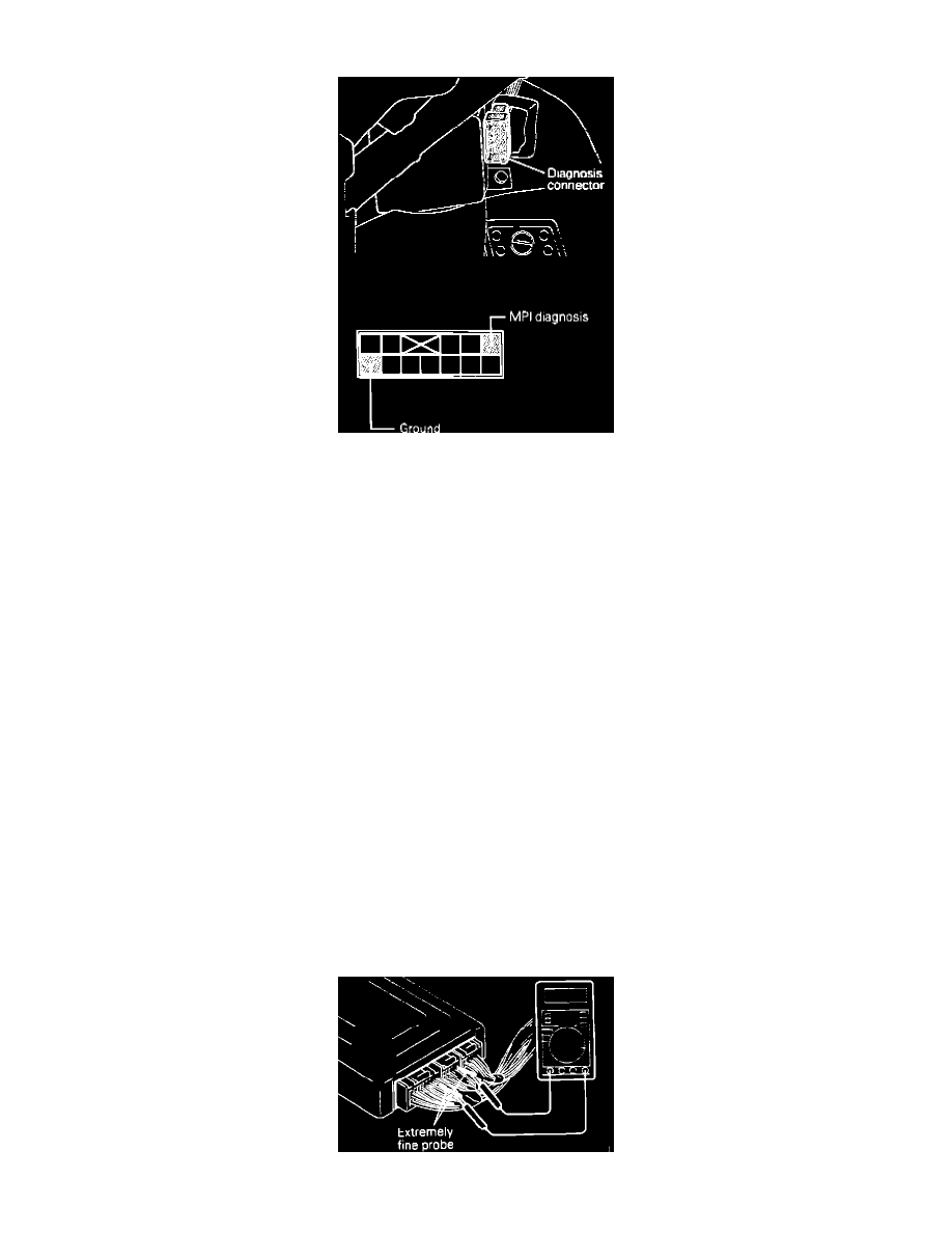
Diagnostic Connector Identification
When checking or correcting engine component malfunctions, check basic engine components prior to troubleshooting the Electronic Control Unit. See:
Powertrain Management/Computers and Control Systems/Testing and Inspection/Initial Inspection and Diagnostic Overview/Diagnostic Strategies
To test the Electronic Control Unit (ECU), located on the right side of the passenger compartment below the dash, proceed as follows:
NOTE: Diagnostic memory is erased if the battery or the ECU connector is disconnected. Do not disconnect the battery before the trouble codes
are completely read. If a sensor connector is disconnected with the ignition switch turned on, the diagnosis code is memorized. In this case,
disconnect the battery negative terminal for 15 seconds or more, and all diagnostic memory will be erased.
1.
Using the procedures contained in ON-BOARD DIAGNOSTICS extract all malfunction codes. Diagnosis memory is erased if the battery or the
ECU connector is disconnected. Do not disconnect the battery before the trouble codes are completely read. See: Powertrain
Management/Computers and Control Systems/Testing and Inspection/Reading and Clearing Diagnostic Trouble Codes/Reading Diagnostic Trouble
Codes
CAUTION: When battery voltage is low, trouble codes cannot be read. Be sure to check the battery for voltage and other conditions before starting
the test.
2.
Does the ECU output a steady 12 VDC at the diagnostic check connector?
a. If not, and the ECU is suspected to be faulty, check the POWER AND GROUND CIRCUITS test to confirm that the ECU is being supplied
with power and ground. See: Main Relay (Computer/Fuel System)/Testing and Inspection/Power and Ground Supply Circuits
b. If so replacement of the ECU is required.
NOTE: Before replacing a ECU that is found to be faulty, insure that no other condition exists that will damage the new unit. This can be best done
by testing the inputs and outputs to the ECU for over voltage/inappropriate power readings or grounds. Use the image in CHASSIS
ELECTRICAL DIAGRAMS and the individual component testing procedures to identify the correct readings for each pin. Check all pins (at the
harness with the ECU removed) that supply a signal to the ECU, for their correct readings and check all other pins to insure that there are no
uncalled for voltage readings or grounds present.
ECU Probing Technique