
3000GT AWD V6-2972cc 3.0L DOHC Turbo 24 Valve (1996)
Insert a feeler gauge between the speed sensor pole piece and the rotor tooth surface and tighten the speed sensor to specified torque where the
clearance is as specified all around.
Standard value: 0.2 - 0.7 mm (.008 - .028 in.)
NOTE: The rear speed sensor pole piece-to-rotor tooth surface clearance is not adjustable in the case of AWD vehicles. In this case, measure
the sensor mounting surface-to-rotor tooth surface clearance.
Standard value: 28.15 - 28.45 mm (1.11 - 1.12 in.)
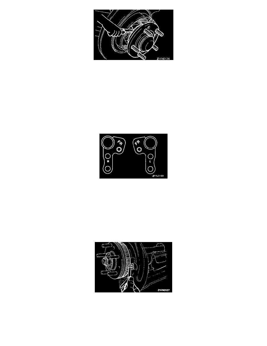
B FRONT SPEED SENSOR BRACKET INSTALLATION
NOTE:
1. The right and left speed sensor brackets differ in shape. Install correctly referring to the identification symbols.
FR: For front speed sensor
R: For right wheel
L: For left wheel
2. After installation of the speed sensor to the bracket, check that the letters "FR" are visible.
C FRONT SPEED SENSOR INSTALLATION
CAUTION: Handle the speed sensor carefully so as not to strike the tip of the pole piece or the rotor teeth against any metal parts and
damage them.
Insert a feeler gauge between the speed sensor pole piece and rotor tooth surface and tighten the speed sensor to specified torque where the
clearance is as specified all around.
Standard value: 0.3 - 0.9 mm (.012 - .035 in.)
INSPECTION