
3000GT VR-4 AWD V6-2972cc 3.0L DOHC MFI Twin Turbo (1998)
CAUTION: In range A, the cam lobe on the camshaft lifts the valve through the rocker arm and the camshaft sprocket is apt to rotate by
reaction force of the valve spring. Therefore, be careful not to have the finger pinched between the sprockets.
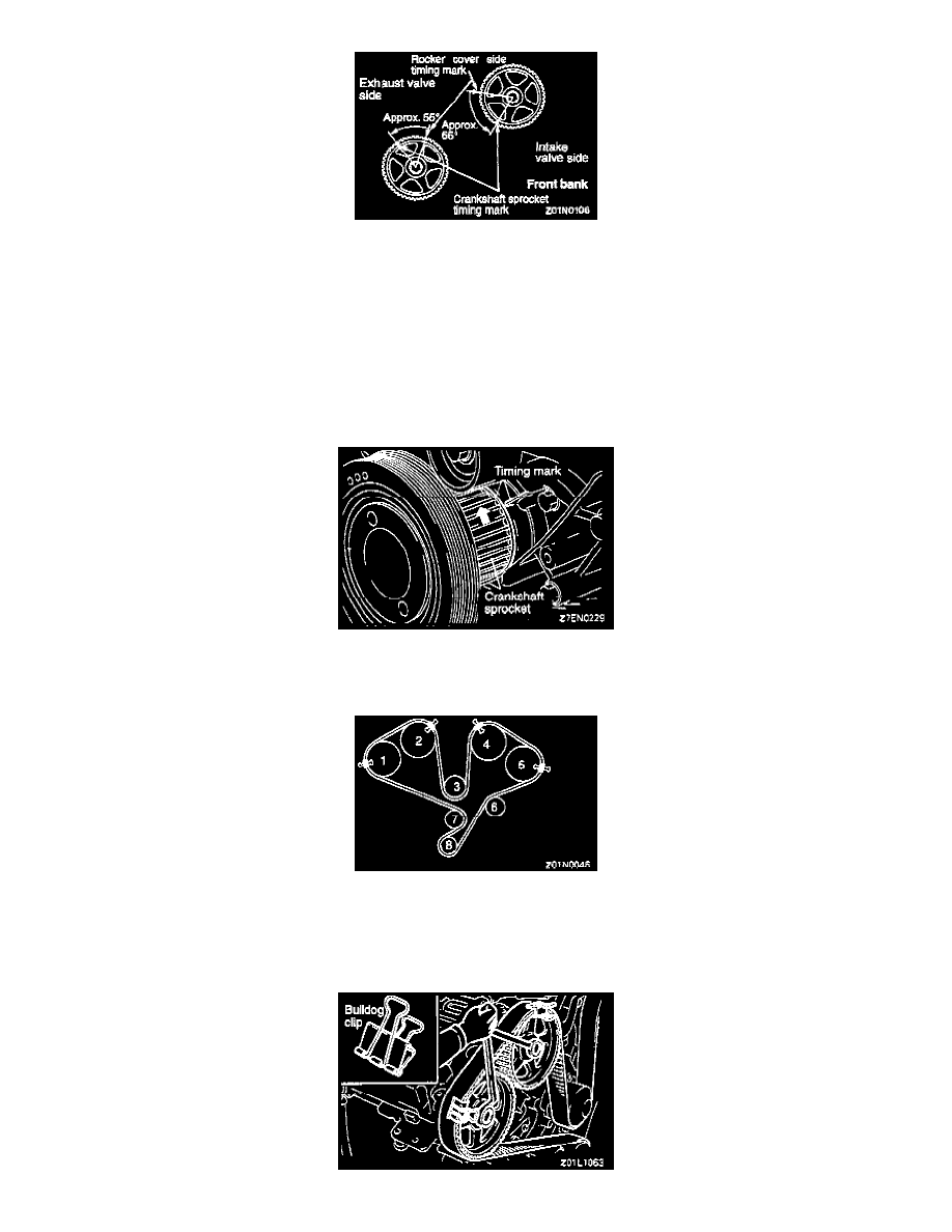
3) Turn the camshaft sprocket for either the intake or exhaust valve to locate the timing mark as shown in the illustration at left. Then turn the
other crankshaft to locate the timing mark as shown in the illustration at left.
CAUTION: If the intake and exhaust valves of the same cylinder lift simultaneously, interference with each other may result. Therefore,
turn the intake valve camshaft sprocket and the exhaust valve camshaft alternately.
4) Turn the camshaft sprocket clockwise to align the timing marks. If the camshaft sprocket has been fumed excessively, turn it
counterclockwise to align the timing marks.
5) Align the timing mark of the crankshaft sprocket.
NOTE: Shift the timing mark of the crankshaft sprocket one tooth in counterclockwise direction to facilitate belt installation.
(2) Using bulldog clips, install the timing belt in the following order with care not to allow the belt to slack
(1) Exhaust camshaft sprocket (front bank side) --> (2) Intake camshaft sprocket (front bank side) --> (3) Water pump pulley --> (4) Intake
camshaft sprocket (rear bank side) --> (5) Exhaust camshaft sprocket --> (6) Idler pulley --> (7) Crankshaft sprocket --> (8) Tensioner pulley
NOTE: Since the camshaft sprockets turn easily, secure them with box wrenches to install the timing belt.