
3000GT VR-4 AWD V6-2972cc 3.0L DOHC MFI Twin Turbo (1998)
Ignition Control Module: Description and Operation
OPERATION
-
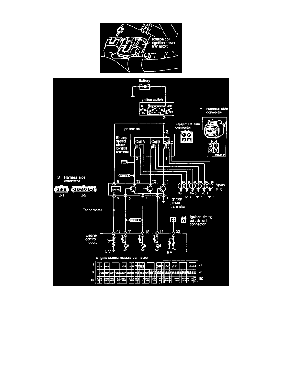
When the ignition power transistor unit A is turned on by the signal from the engine control module, primary current flows to the ignition coil A.
When the ignition power transistor unit A is turned off, the primary current is shut off and a high voltage is induced in the secondary coil A,
causing the ignition plugs of No. 1 and No. 4 cylinders to spark. When the ignition power transistor unit B is turned off, the ignition plugs of No. 2
and No. 5 cylinders spark. In addition, when the ignition power transistor unit C is turned off, the ignition plugs of No. 3 and No. 6 cylinders
spark.
-
When the engine control module turns off the transistor in the module, the battery voltage in the module is applied to the ignition power transistor
unit to turn it on. When the engine control module turns on the transistor in the module, the ignition power transistor unit is turned off.