
3000GT VR-4 AWD V6-2972cc 3.0L DOHC MFI Twin Turbo (1998)
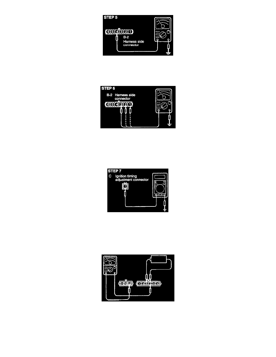
Check for continuity of the ground circuit.
-
Connector: Disconnected
OK: GO TO STEP 6
NG: Repair the harness. (B4 - Ground)
Measure the voltage of the control signal circuit of the ignition power transistor.
-
Connector: Disconnected
-
Ignition switch: START
Voltage (V): 0.5 - 4.0
OK: GO TO STEP 7
NG: Repair the harness. (B3-11) (B2-12) (B1-13)
Measure the voltage of the ignition timing adjustment terminal.
-
Ignition switch: ON
Voltage (V): 4.0 - 5.2
OK: STOP
NG: Repair the harness. (C1-23)
Ignition Power Transistor
NOTE: An analog-type circuit tester should be used.
No. 1-No. 4 coil side
1. Connect the negative (-) terminal of the 1.5 V power supply to terminal (4) of the ignition power transistor; then check whether there is continuity
between terminal (13) and terminal (4) when terminal (3) and the positive (+) terminal are connected and disconnected.
NOTE: Connect the (-) probe of the circuit tester to terminal (13).