
3000GT VR-4 AWD V6-2972cc 3.0L DOHC MFI Twin Turbo (1998)
<B> Self-Locking Nut Removal (8)
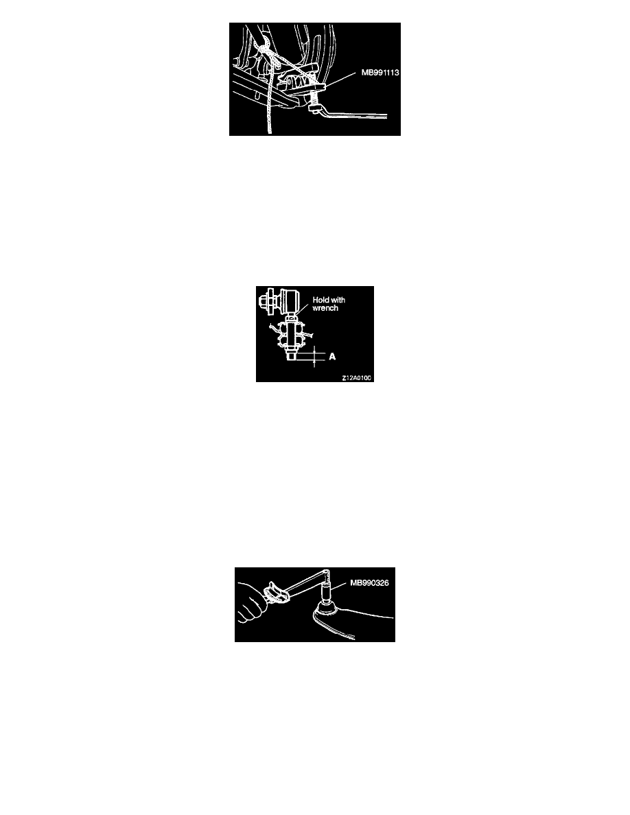
Lower down the lower arm on the crossmember side. Then, install the special tool and disconnect the lower arm ball joint from the knuckle.
CAUTION: Support special tool MB991113 with a cord, etc. to prevent it from coming off.
NOTE: Only loosen the nut, do not remove it from the ball joint.
INSTALLATION
Installation in reverse order as removal.
Installation Service Points
>A< Stabilizer Link To Lower Arm Coupling Nut Installation (7)
Holding the stabilizer link with a wrench, tighten the self-locking nut so that the protrusion of the stabilizer link (dimension A indicated in
illustration) is within the standard value.
Standard value (A): 5 - 7 mm (0.197 - 0.276 inch)
Post-installation Operation
1. Check the dust cover for cracks or damage by pushing it with finger.
2. Wheel alignment check and adjust.
INSPECTION
-
Check the bushing for wear and deterioration.
-
Check the upper or lower arm for bend or breakage.
-
Check all bolts for condition and straightness.
Ball Joint Breakaway Torque Check
1. After shaking the ball joint stud several times, install the nut to the stud and use the special tool to measure the breakaway torque of the ball
joint.
Standard value: 2 - 9 Nm (17 - 78 inch lbs.)
2. When the measured value exceeds the standard value, replace the arm assembly.
3. When the measured value is lower than the standard value, check that the ball joint turns smoothly without excessive play. If so, it is possible
to use that ball joint.
Ball Joint Dust Cover Inspection