
Cordia L4-2.0L SOHC (1984)
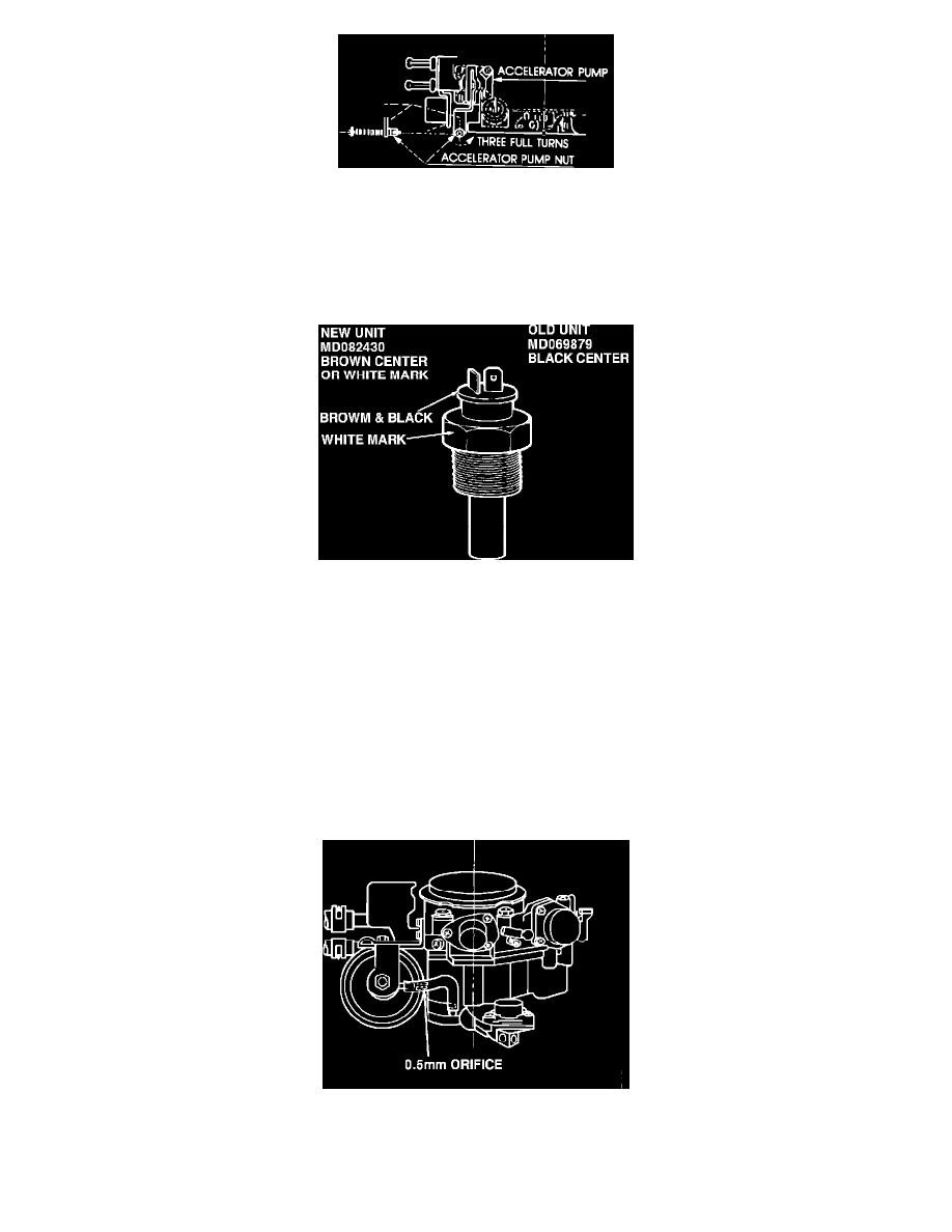
FIGURE 9
3.
Use the special accelerator pump adjusting tool you have made to unscrew the accelerator pump nut counterclockwise three (3) full turns. See
Figure 9.
NOTE:
If you are uncertain whether this operation has already been performed, check to see if the nut is flush with the end of the rod. If it is, then
this operation has already been performed.
FIGURE 10
4.
Inspect the coolant temperature sensor mounted on top of the intake manifold. If it has a black center, it is an early unit and must be replaced. See
Figure 10. If it has a brown center or is marked with white paint, it is the new unit and does not have to be replaced. To replace the sensor, do the
following:
a.
Drain enough coolant to bring the level below the temperature sensor.
b.
Disconnect the battery ground cable and the sensor harness.
c.
Unscrew the temperature sensor.
d.
Apply pipe thread sealant to the threads of the replacement sensor and install it. Tighten to 30-39 N-m (22-28 ft.-lbs.) Re-connect the battery
cable and replenish the engine coolant.
FIGURE 11
5.
Pull the end of the vacuum line off the secondary throttle depression chamber (vacuum actuator) and insert the #50 orifice as shown in Figure 11.
Push the vacuum line back on its nipple.