
Cordia L4-2.0L SOHC (1984)
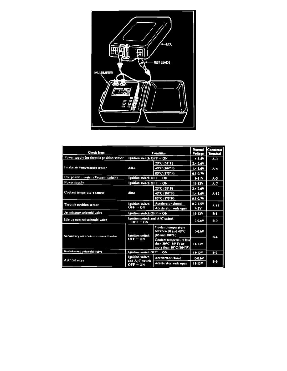
Figure 2
TEST PROCEDURE
1.
Remove the cowl side panel to reach the computer terminal connectors.
2.
Attach the black (-) lead of the voltmeter to a good ground, such as the computer box.
3.
Refer to the 1984 FBC System Voltmeter Check Chart I (see page 3). Note the connector terminal callouts in the right column. Insert the positive
probe into each connector terminal in turn. Switch the ignition from OFF to ON, and compare the voltage with that shown in the chart. For
example, when the probe is on terminal A13, the voltmeter should read between 0.2 and 1.5V as shown in Figure 2 with the accelerator closed,
and 4-5V when the accelerator is open.
4.
Proceed until you have checked all of the terminals in Chart I, or until a voltage is found that is out of specification. If all voltages are within
specification, go to Step 6. If a voltage is out of specification, go to Step 5.