
Cordia L4-2.0L SOHC (1984)
Oxygen Sensor: Technical Service Bulletins
FBC System - Voltmeter Check Procedure
NO.
STB-84-14-012
DATE
June, 1984
MODEL
1984 2.0L Cordia/Tredia
SUBJECT:
1984 FBC SYSTEM VOLTMETER CHECK PROCEDURE
USE OF VOLTMETER TO TEST FBC SYSTEM
The FBC electronic systems on 1984 Cordia/Tredia 2.0L models can be checked using your digital multimeter or any high-impedance voltmeter. This
method is useful when you want to check the FBC system without unplugging the connectors, or when an ECI checker is not available.
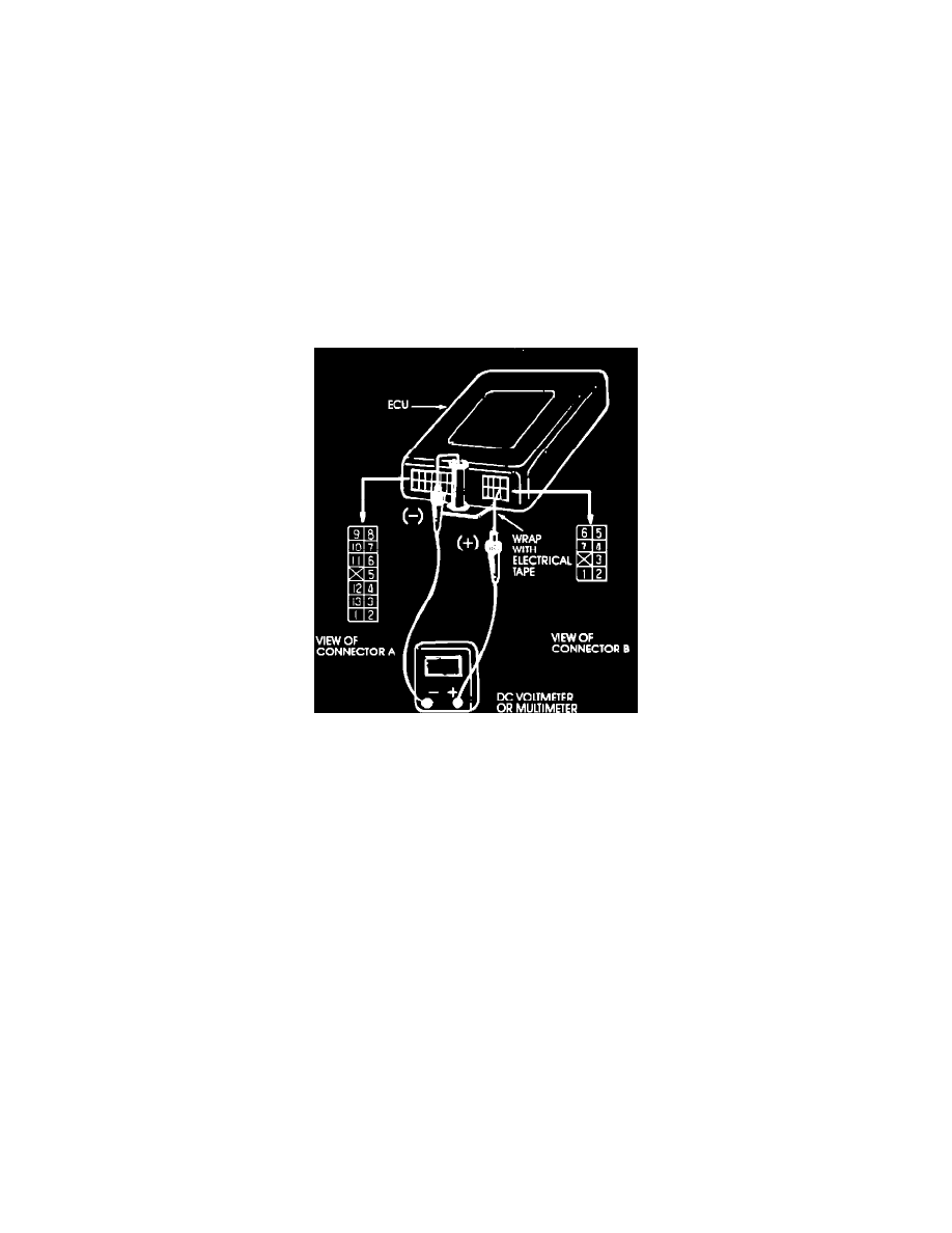
Figure 1
VOLTMETER PROBES AND CONNECTIONS
To perform the FBC system tests, you will measure voltages right at the computer which is on the right cowl kick panel. Make up a set of thin probes
(paper clips work fine) to attach to your voltmeter and insert into the tops of the connectors on the computer as shown in Figure 1. You don't have to
unplug the connectors.
CAUTION: Short-circuiting the positive (+) probe between a connector terminal and ground could damage the vehicle wiring, the sensor, the ECU, or
all three. Use care to avoid it! Insulate the exposed part of the probe with electrical tape as a precaution.