
Cordia L4-2.0L SOHC (1984)
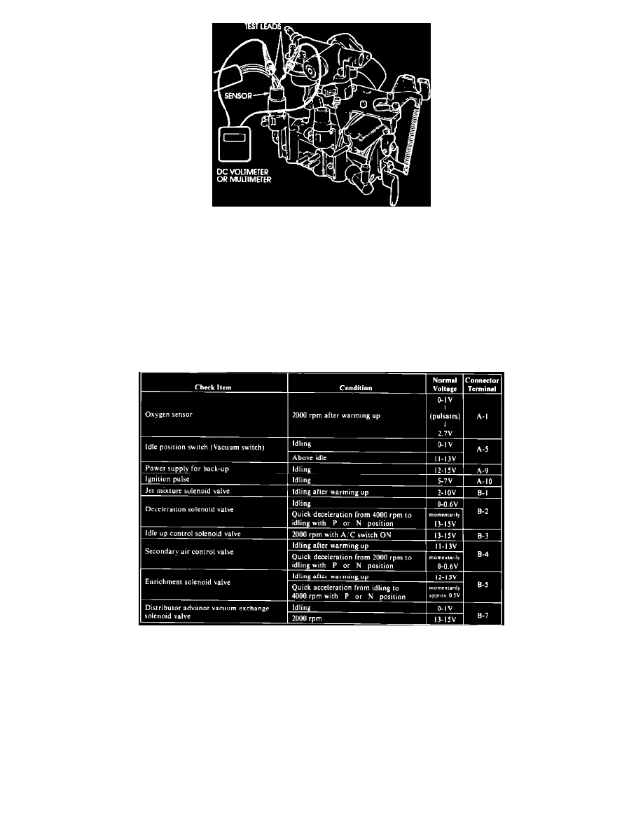
Figure 3
5.
When you find a voltage that is out of specification (except TPS), measure sensor voltage output at the sensor terminal on the same color wire as
in the computer terminal for that sensor. Figure 3 shows a typical example. This tells you whether the voltage variation is in the sensor or the
connectors and wiring.
Correct any loose connections, replace sensors as required, and then disconnect the battery for 30 seconds to erase the computer's memory of the
malfunction. Re-check the appropriate terminal to verify that the malfunction has been corrected.
NOTE:
If the TPS voltage is out of specification, remember that the TPS produces a failure signal if the throttle has been blipped when shutting down
the engine. Re-start the engine and then let it stop without depressing the accelerator. Then measure the TPS voltage at the computer, and, if
necessary, at the sensor connector.
6.
Perform the checks in Chart II. If an out-ofspecification voltage is found, measure the sensor output right at the connector. If OK, then you know
the wiring or connector is the source of the discrepancy.
NOTE:
If the oxygen sensor voltage is out of specification, drive the car until it is warm enough to activate the oxygen sensor and then without
shutting off the engine, measure the voltage output of the oxygen sensor at the computer.
7.
Correct connections and replace sensors as required, and then disconnect the car's battery for 30 seconds to erase the computer's memory of the
malfunction. Re-check the appropriate terminal to verify that the malfunction has been corrected.
NOTE:
To avoid damage to the ECU, be sure the ignition is OFF before disconnecting the battery.