
Diamante V6-2972cc 3.0L SOHC (1992)
Crankshaft Position Sensor: Description and Operation
Distributor Assembly
LOCATION
Housed in distributor.
PURPOSE
The Electronic Control Module (ECM) uses this input to determine engine speed and crankshaft position, and adjusts ignition timing, fuel
injection, and idle speed accordingly.
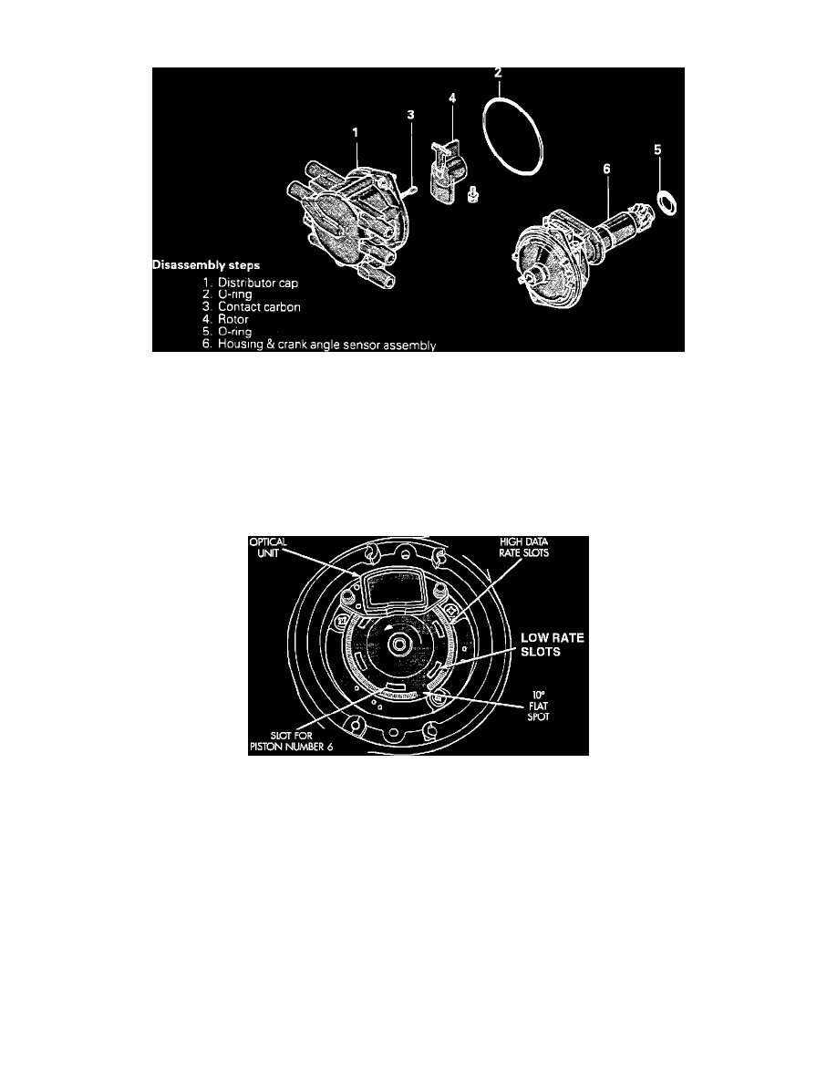
Optical Distributor Top View
OPERATION
A thin disk, with 2 sets of slots, spins at half engine speed, between two LED and photo diode pairs (optical sensors).
Generates pulses when slots pass between Light Emitting Diodes (LED's) and photo diodes.
Based on these signals, the Control Unit is able to determine the fuel injection pulse width, ignition timing, and also the intake air flow rate for
each revolution of the engine.
High Data Rate Slots
The outer or "high data rate", slots pass through the corresponding optical sensor 1 slot per 2 degrees of crankshaft rotation.
This high data rate, set of slots is used for ignition timing for engine speeds up to 1200 rpm, where speed changes due to individual firing pulses
are significant, to increase timing accuracy.