
Diamante V6-2972cc 3.0L SOHC (1992)
Barometric Pressure Sensor: Testing and Inspection
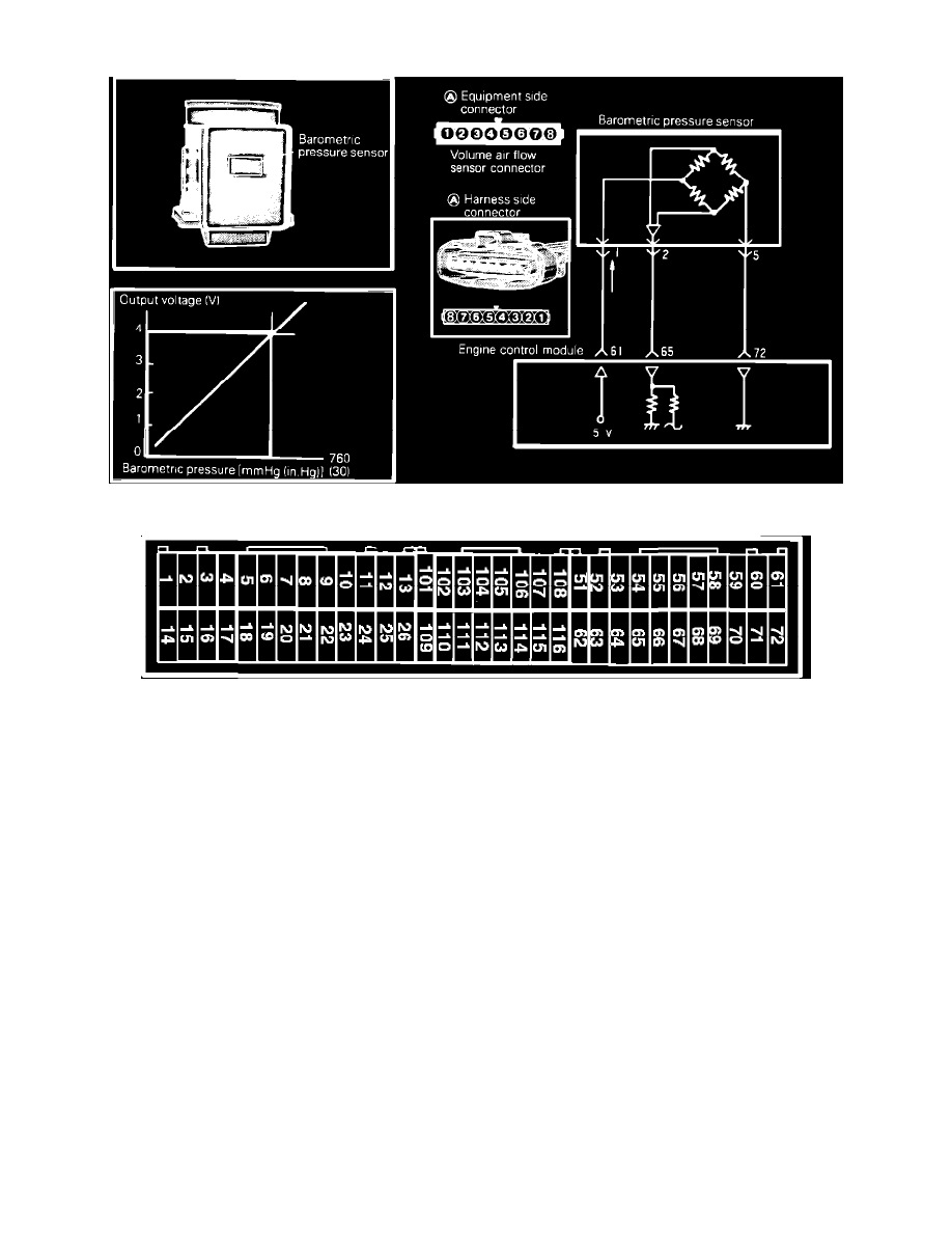
Barometric Sensor
Engine Control Module Connector--For Pin Applications See Components
To test the Barometric Pressure Sensor, located on the air flow sensor, in the air cleaner housing, proceed as follows.
COMPONENT TEST
1.
Connect a voltmeter between terminals 5 and 2 of the AFS Sensor connector.
Terminal 2: Barometric sensor output
Terminal 5: sensor ground
Terminal 1: sensor 5 Volt power
Voltage (W/ key on and engine off)
- At sea level
Approximately 4.0 volts.
- At 2,000 ft.
Approximately 3.75 volts.
- At 4,000 ft.
Approximately 3.50 volts.
- At 6,000 ft.
Approximately 3.25 volts.
2.
Warm the engine and bring it to a normal idle.
3.
Slowly cover about half of the air cleaner air intake, observing the change in voltage. As pressure falls (vacuum increases), you should observe a
drop in voltage.
HARNESS TEST
1.
Disconnect the air flow sensor connector and turn the key to the ON position.
2.
Using a voltmeter, measure the power supply voltage between the harness connector terminal 1 and ground.