
Diamante V6-2972cc 3.0L SOHC (1992)
Waveforms
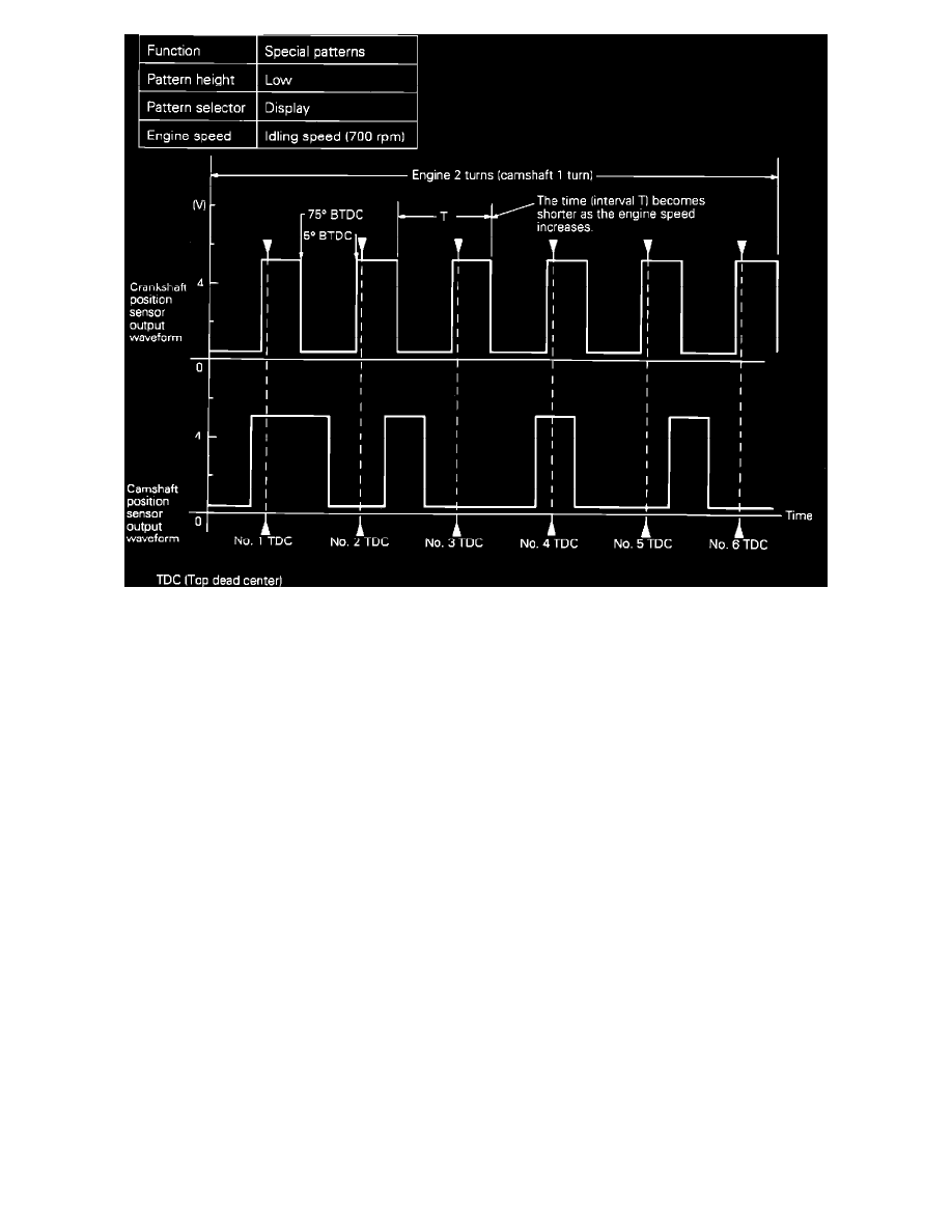
2.
Check the waveform and compare it to the diagram shown.
3.
If scope pattern is not as depicted in image, continue with the rest of the test procedures before replacing the assembly.
VOLTAGE TESTING PROCEDURE:
1.
Connect a voltmeter between terminal 2 (Crankshaft Position signal), and 4 (Sensor ground), of the crank angle sensor connector.
2.
Observe the output voltage while cranking the engine.
Standard Approximate Values
1.8 - 2.5 Volts (needle fluctuates)
3.
If the voltage is abnormal, check the sensor power and ground circuits.
HARNESS TEST:
1.
Disconnect the crankshaft position/camshaft (TDC) sensor connector and turn the key to the ON position.
2.
Using a voltmeter, measure the voltage between the harness connector terminal 3 and ground.
Expected Voltage:
System voltage.
3.
Check for continuity between the crankshaft position/camshaft (TDC) sensor harness connector terminal 4 and ground.
Continuity:
Should exist.
4.
Using a voltmeter, measure the output circuit voltage between the harness connector terminal 2 and ground.