
Diamante Sedan V6-2972cc 3.0L DOHC (1993)
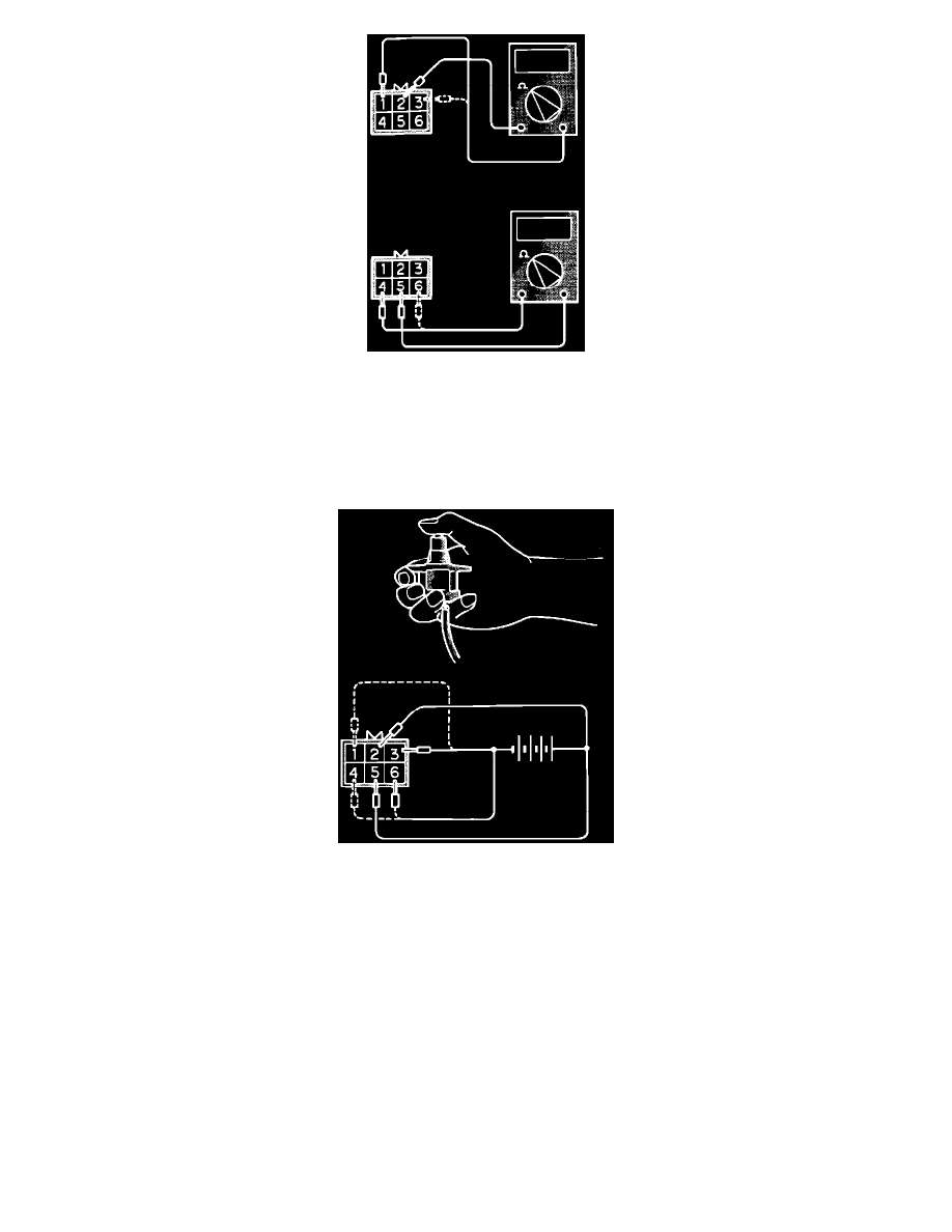
Idle Speed Control (ISC) Servo Resistance Test
2. Using an ohm meter, check the resistance between terminals 2 and 1 and 2 and 3.
Resistance 28 - 33 ohms @ 68°F
3. Using an ohm meter, check the resistance between terminals 5 and 6 and 5 and 4.
Resistance 28 - 33 ohms @ 68°F
Idle Speed Control (ISC) Servo Operation Test
CAUTION: Do not apply a voltage higher than 6 Volts. If a higher voltage is used, damage to the IAC motor can result.
4. Using a 6 VDC power supply, apply voltage to terminals 2 and 5.
5. While holding the motor as indicated in the image, connect the negative terminal of the supply to each pair of terminals in the order given below.
The motor should vibrate when the ground circuit is supplied.
a. Connect the negative power supply to terminals 3 and 6.
b. Connect the negative power supply to terminals 1 and 6.
c. Connect the negative power supply to terminals 1 and 4.
d. Connect the negative power supply to terminals 3 and 4.
e. Connect the negative power supply to terminals 3 and 6.
f.
Perform the tests in reverse order from step e to a.
6. Replace the motor if does not vibrate during each test.
OSCILLOSCOPE TEST
1. Connect the probe of the scope to the four points shown in the image.