
Diamante Sedan V6-2972cc 3.0L DOHC (1993)
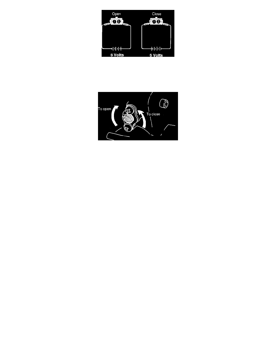
Variable Induction Control Servo, Operational Test Hook-up
CAUTION: If a voltage higher than 6 volts dc is applied to the VICS, damage to the servo gears can occur.
3.
Connect a voltage source not exceeding "6 VDC" to component connector terminals 1 and 2.
Variable Induction Control Valve Operation
4.
Verify that the control valve shaft turns smoothly in either direction as the polarity of the voltage source is reversed.
HARNESS TEST
1.
Disconnect the VICS harness and ECM connectors.
2.
Using an ohm meter, check for continuity between VICS harness connector terminal 1 and ECM harness 109.
Continuity
Should exist
3.
Using an ohm meter, check for continuity between VICS harness connector terminal 2 and ECM harness 110.
Continuity
Should exist
4.
Using an ohm meter, check for continuity (shorts) between VICS harness connector terminal 1 and ground.
Continuity
Should not exist
5.
Using an ohm meter, check for continuity (shorts) between VICS harness connector terminal 2 and ground.
Continuity
Should not exist
6.
Using an ohm meter, check for continuity (shorts) between ECM harness connector terminal 109 and ground.
Continuity
Should not exist
7.
Using an ohm meter, check for continuity (shorts) between ECM harness connector terminal 110 and ground.
Continuity
Should not exist
If any of the previous tests produce unsatisfactory results, the harness will need to be repaired or replaced. Once repairs have been completed,
confirm that the repair has corrected the problem.