
Diamante Sedan V6-2972cc 3.0L DOHC (1993)
Ignition Control Module: Testing and Inspection
Power Transistor
NOTE: An analog-type circuit tester should be used.
No. 1 - No. 4 Coil Side
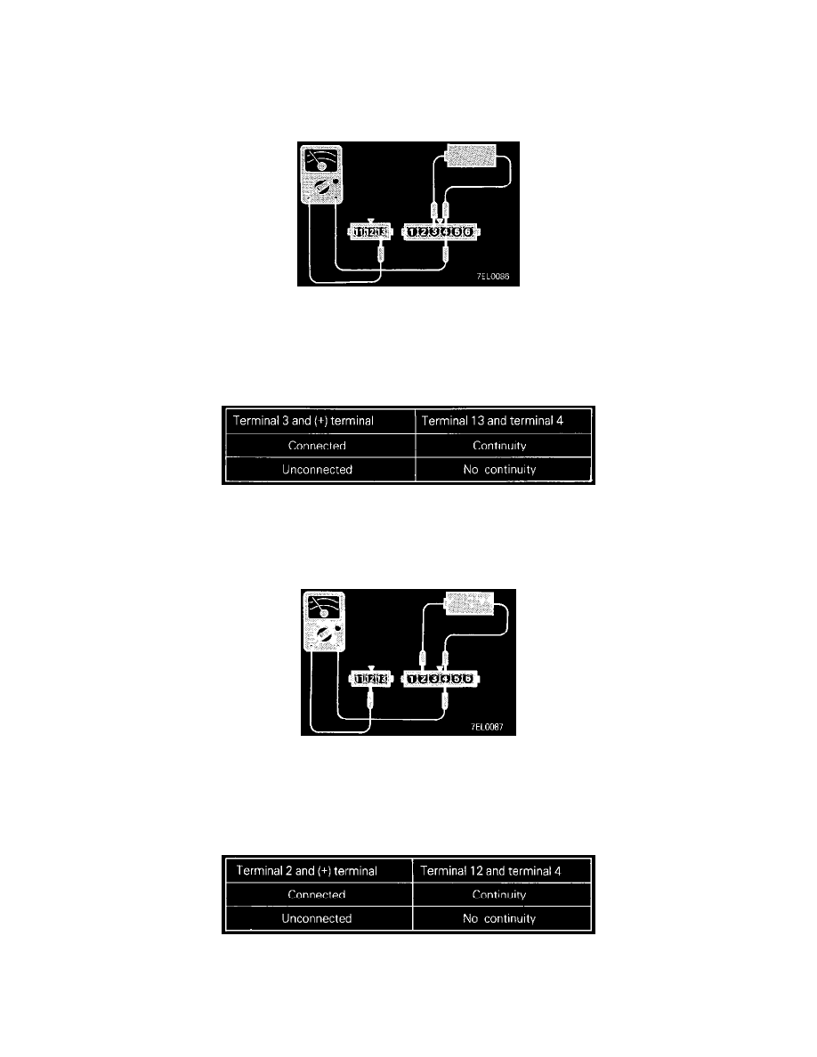
Ignition Power Transistor Continuity Check
1. Connect the negative (-) terminal of the 1.5 V power supply to terminal (4) of the ignition power transistor; then check whether there is continuity
between terminal (13) and terminal (4) when terminal (3) and the positive (+) terminal are connected and disconnected.
NOTE: Connect (-) Probe of the circuit tester to terminal (13).
Ignition Power Transistor Continuity Check Table
2. Replace the ignition power transistor if there is a malfunction.
No. 2 - No. 5 Coil Side
Ignition Power Transistor Continuity Check
1. Connect the negative (-) terminal of the 1.5 V power supply to terminal (4) of the ignition power transistor; then check whether there is continuity
between terminal (12) and terminal (4) when terminal (2) and the positive (+) terminal are connected and disconnected.
NOTE: Connect the (-) probe of the circuit tester to terminal (12).
Ignition Power Transistor Continuity Check Table
2. Replace the ignition power transistor if there is a malfunction.