
Eclipse L4-1795cc 1.8L SOHC (1990)
Engine Control Module: Component Tests and General Diagnostics
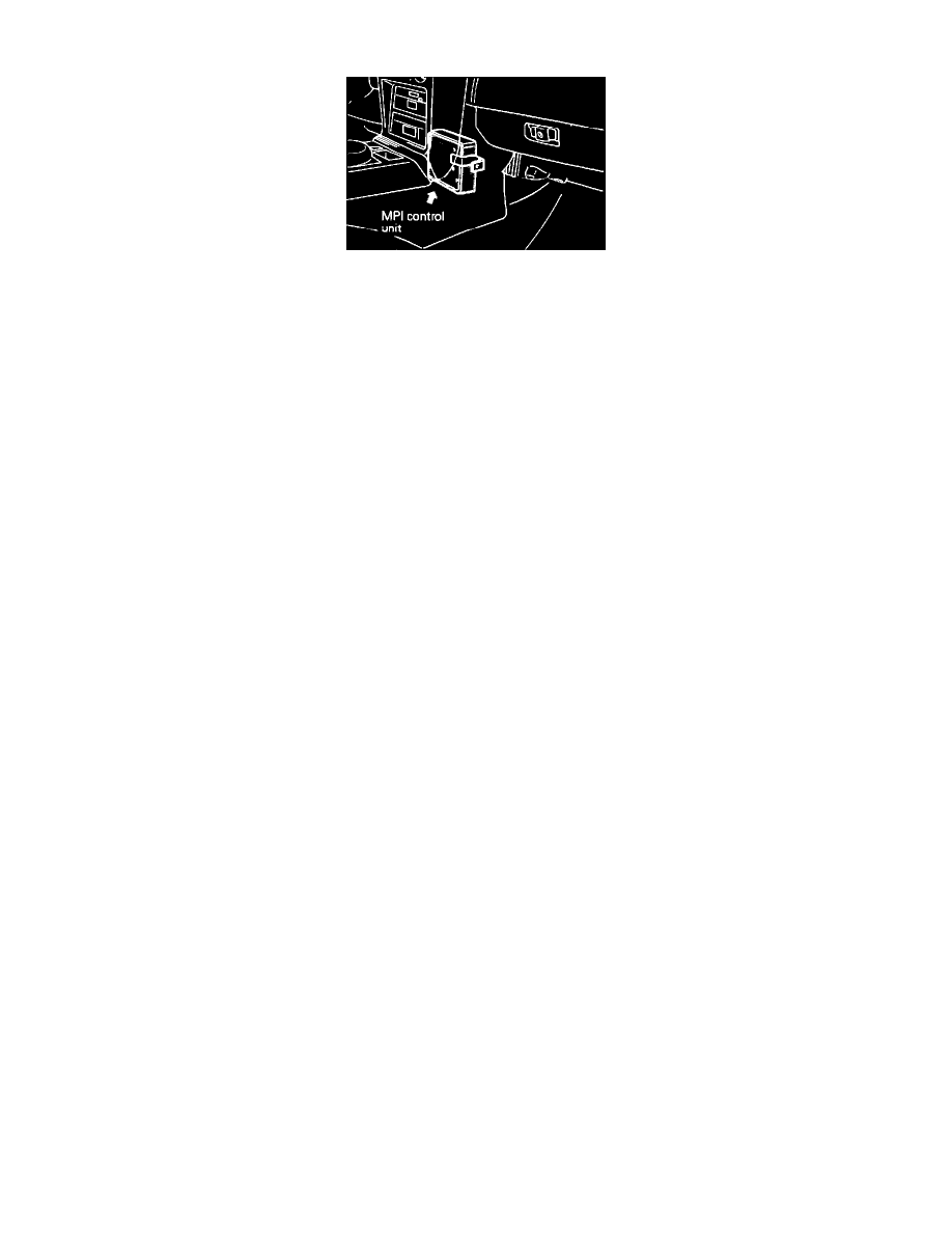
Detailed Component Locations - Electronic Control Unit
To test the Electronic Control Unit (ECU), located in front of the center console, proceed as follows:
NOTE: Diagnostic memory is erased if the battery or the ECU connector is disconnected. Do not disconnect the battery before the trouble codes
are completely read.
NOTE: If a sensor connector is disconnected with the ignition switch turned on, the diagnosis code is memorized. In this case, disconnect the
battery negative terminal for 15 seconds or more, and all diagnostic memory will be erased.
1.
Using the procedures contained in ON-BOARD DIAGNOSTICS extract all malfunction codes. Diagnosis memory is erased if the battery or the
ECU connector is disconnected. Do not disconnect the battery before the trouble codes are completely read.
CAUTION: When battery Voltage is low, trouble codes cannot be read. Be sure to check the battery for Voltage and other conditions before
starting the test.
2.
Does the ECU output a steady 12 VDC at the check connector?
a. If not, and the ECU is suspected to be faulty, check the POWER AND GROUND CIRCUITS test to confirm that the ECU is being supplied
with power and ground.
b. If so replacement of the ECU is required.
NOTE: Before replacing a ECU that is found to be faulty, insure that no other condition exists that will damage the new unit. This can be best done
by testing the inputs and outputs to the ECU for over Voltage/inappropriate power readings or grounds. Use the image in CHASSIS
ELECTRICAL DIAGRAMS and the individual component testing procedures to identify the correct readings for each pin. Check all pins (at the
harness with the ECU removed) that supply a signal to the ECU, for their correct readings and check all other pins to insure that there are no
uncalled for Voltage readings or grounds present.
3.
Compare all the remaining codes to the following list and perform the required inspections called for in each of the categories that are affected by a
code.
Check power supply for:
1. Faulty battery.
2. Faulty fusible link.
3. Faulty fuse.
4. Check for faulty body ground.
Check Fuel supply for:
1. Damaged fuel line.
2. Clogged or damaged fuel filter.
3. Faulty fuel pump.
Check ignition system for:
1. Faulty spark plugs.
2. Faulty ignition wiring.
3. Faulty distributor.
4. Faulty ignition coil.
Check emission control system for:
1. Faulty PCV system.
2. Faulty EGR system.
3. Vacuum leak.
4. Ignition timing and idle speed.
All categories:
ECU system faults are often caused by poor harness contact, therefore check that all of the connectors in all of the affected systems are secure and
have continuity.
4.
After completing all of the system inspections required in step 3, proceed to the ECU Codes in ON-BOARD DIAGNOSTICS and refer to "Check
item (Remedy) column" of the images supplied with "extracting fault codes". Perform all of the inspections and component tests (refer to