
Eclipse L4-1996cc 2.0L DOHC (1995)
Connecting Rod: Service and Repair
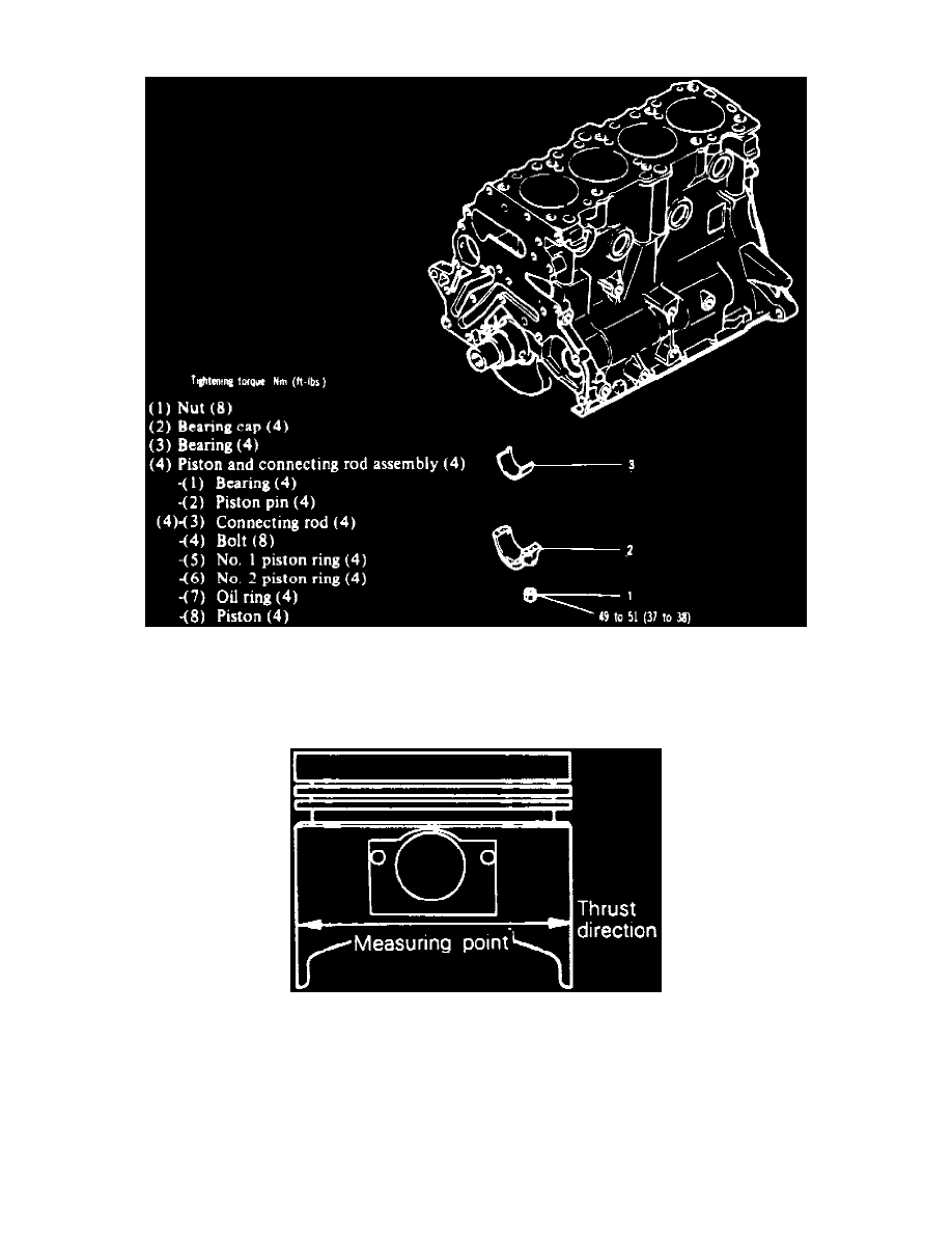
Fig. 73 Piston & Rod Disassembly
Refer to Fig. 73 when removing piston and rod assembly. Keep all components, such as connecting rod caps and bearings, in proper order for
installation. Position each piston ring gap as far apart as possible and ensure each piston and rod are installed in the same cylinder bore as removed.
Ensure connecting rod caps and bearings are placed on proper connecting rods, then tighten bolts to specification.
Fig. 74 Piston Measurements
Pistons and rings are available in standard sizes and oversizes of 0.010, 0.020, 0.030 and 0.039 inch. Measure piston as shown, Fig. 74. Oversize pins
are not available.