
Eclipse V6-3.0L SOHC (2003)
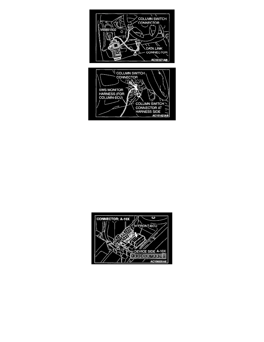
1. Connect scan tool MB991502 to the data link connector.
2. Connect SWS monitor kit MB991862 to the column switch connector.
3. Turn the ignition switch to the "LOCK" (OFF) position.
4. Operate the MUT-II according to the procedure below to display "ECU COMM CHECK."
1. Select "SYSTEM SELECT."
2. Select "SWS."
3. Select "SWS MONITOR."
4. Select "ECU COMM CHECK."
5. Scan tool MB991502 should show "OK" on the "ETACS ECU" menu.
Q: Is "OK" displayed on the "ETACS ECU" menu?
YES: Go to Step 2.
NO: Refer to Inspection Procedure A-3 "Communication with ETACS-ECU is impossible."
STEP 2. Measure at front-ECU connector A-10X in order to check the battery circuit of power supply system to the front-ECU.
1. Disconnect front-ECU connector A-10X, and measure at the relay box side.