
Eclipse V6-3.0L SOHC (2003)
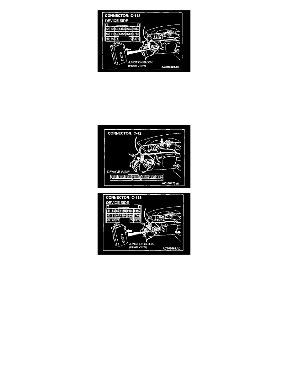
STEP 8. Check combination meter connector C-42 and ETACS-ECU connector C-118 for damage.
Q: Are combination meter connector C-42 and ETACS-ECU connector C-118 in good condition?
YES: Go to Step 9.
NO: Repair or replace the connector. Refer to Harness Connector Inspection. The theft-alarm indicator light should illuminate, and the theft-alarm
system should be set normally.
STEP 9. Check the wiring harness between combination meter connector C-42 (terminal 31) and ETACS-ECU connector C-118 (terminal 74).
Q: Is the wiring harness between combination meter connector C-42 (terminal 31) and ETACS-ECU connector C-118 (terminal 74) in good condition?
YES: No action to be taken.
NO: Repair the wiring harness. The theft-alarm indicator light should illuminate, and the theft-alarm system should be set normally.
STEP 10. Check the input signal by using "DATA LIST" of the SWS monitor.
Satisfy the following conditions to check the driver's and front passenger's door switches.
-
Driver's door: Open (driver's door switch is on)
However, the door should be closed when checking the front passenger's door switch.
-
Front passenger's door: Open (front passenger's door switch is on)
However, the door should be closed when checking the driver's door switch.
CAUTION: To prevent damage to scan tool MB991502, always turn the ignition switch to the "LOCK" (OFF) position before connecting or
disconnecting scan tool MB991502. Also connect SWS monitor kit MB991862 after turning on scan tool MB991502.