Eclipse GT V6-3.0L SOHC (2000)

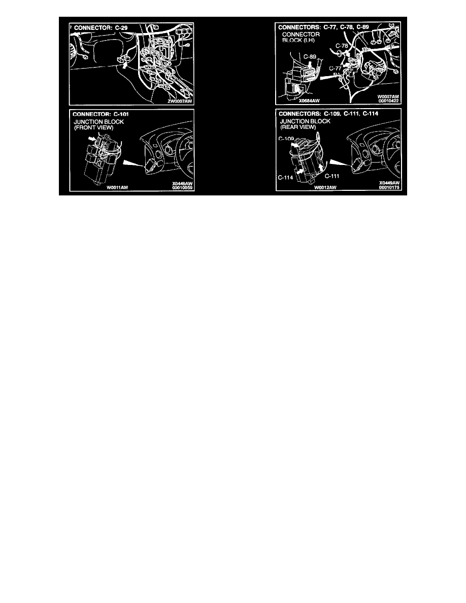
Connectors
CIRCUIT OPERATION
The ETACS-ECU receives a diagnostic trouble code and switch signals from the data link connector.
TECHNICAL DESCRIPTION (COMMENT)
The harness wires between the ETACS-ECU power supply line or the ETACS-ECU and the data link connector may be defective.
TROUBLESHOOTING HINTS
-
Malfunction of the ETACS-ECU
-
Damaged harness wires or connectors
DIAGNOSIS
Required Special Tools:
MB991223: Harness Set
MB991502: Scan Tool (MUT-II)
MB991529: Diagnostic Trouble Code Check Harness
STEP 1. Check the communication with other systems.
If the scan tool can not communicate with all systems, refer to Diagnosis (Computers/Testing).
If the scan tool can not communicate with the SWS only, go to Step 2.
STEP 2. Check the ignition switch positions.
If scan tool MB991502 can communicate with the ETACS-ECU with the ignition switch at "ON" position, check the ETACS-ECU battery circuits.
Refer to Inspection Procedure P-1.
See: Symptom Diagnostic Procedures/P - Charts
If scan tool MB991502 can communicate with the ETACS-ECU regardless of the ignition switch position, go to Step 3.
