
Eclipse GT V6-3.0L SOHC (2000)
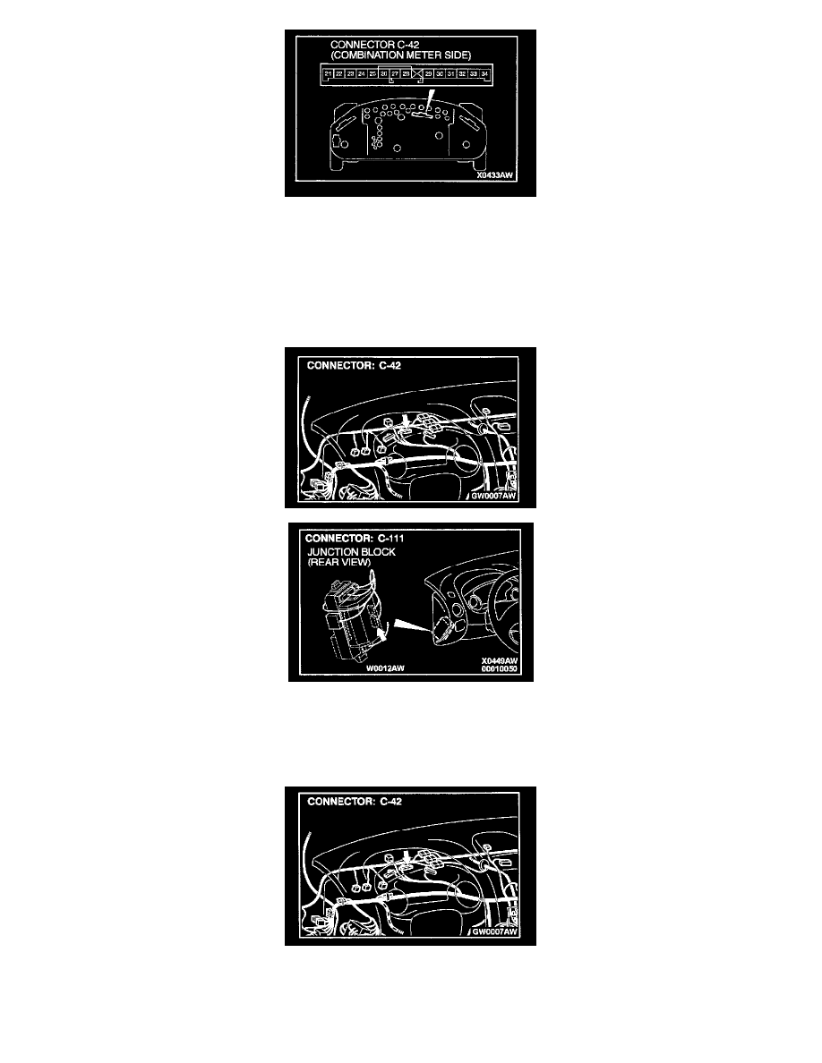
STEP 4. Check the combination meter (printed-circuit board).
1. Remove the combination meter.
2. Remove the high-beam indicator light bulb. Then measure the resistance between the bulb terminals.
3. Install the bulb to the combination meter, and then measure the resistance between connector C-42 terminals 21 and 22. The resistance reading at
this time should be much the same as the resistance measured at Step (2).
If the two resistance values are extremely different each other, repair or replace the combination meter (printed-circuit board).
The high-beam indicator light should illuminate.
If the two resistance values are much the same, go to Step 5.
STEP 5. Check the combination meter connector C-42 and ETACS-ECU connector C-111 for damage.
If the combination meter connector C-42 and ETACS-ECU connector C-111 are damaged, repair or replace them. Refer to Harness Connector
Inspection. The high-beam indicator light should illuminate.
If the connectors are in good condition, go to Step 6.