
Eclipse GT V6-3.0L SOHC (2000)
STEP 7. Check the harness wires between ETACS-ECU connector C-114 and battery.
NOTE: After checking junction block connector C-104 and intermediate connector C-89, check the wires. If junction block connector C-104 and
intermediate connector C-89 are damaged, repair or replace them. Refer to Harness Connector Inspection.
If the harness wires between ETACS-ECU connector C-114 and battery are damaged, repair them.
The turn-signal lights should flash normally.
STEP 8. Check the input signal.
Check the input signals from the following switches.
-
Ignition switch (IG1)
-
Turn-signal light switch
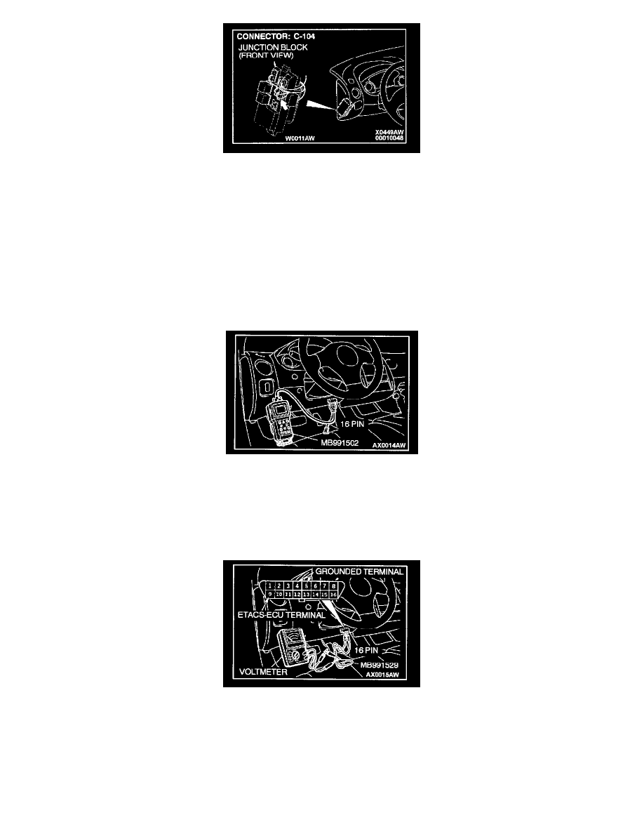
<When using scan tool MB991502>
CAUTION: To prevent damage to scan tool MB991502, always turn the ignition switch to "LOCK" (OFF) position before connecting or disconnecting
scan tool MB991502.
1. Connect scan tool MB991502 to the data link connector.
2. Check that the tone alarm of scan tool MB991502 sounds when the input signal enters.
<When using a voltmeter>
1. Use special tool MB991529 to connect a voltmeter between ground terminal 4 or 5 and ETACS-ECU terminal 9 of the data link connector.
2. Check that the voltmeter indicator deflects once when the input signal enters.
If one of the input signal checks shows a defect, check the relevant input circuit.
If no defect appears, replace the ETACS-ECU. The turn-signal lights should flash normally.
Inspection Procedure K-2