
Eclipse GT V6-3.0L SOHC (2000)
-
Theft-alarm system <vehicles with theft alarm system>
If no functions work normally, check the ETACS-ECU battery circuit. Refer to Inspection Procedure P-1.
See: Symptom Diagnostic Procedures/P - Charts
If any of the functions work, go to Step 2.
STEP 2. Check the input signal.
Check the input signals from the following switches:
-
Ignition switch (IG1)
-
Key reminder switch
-
Driver's and passenger's door switch
-
Driver's door lock actuator switch
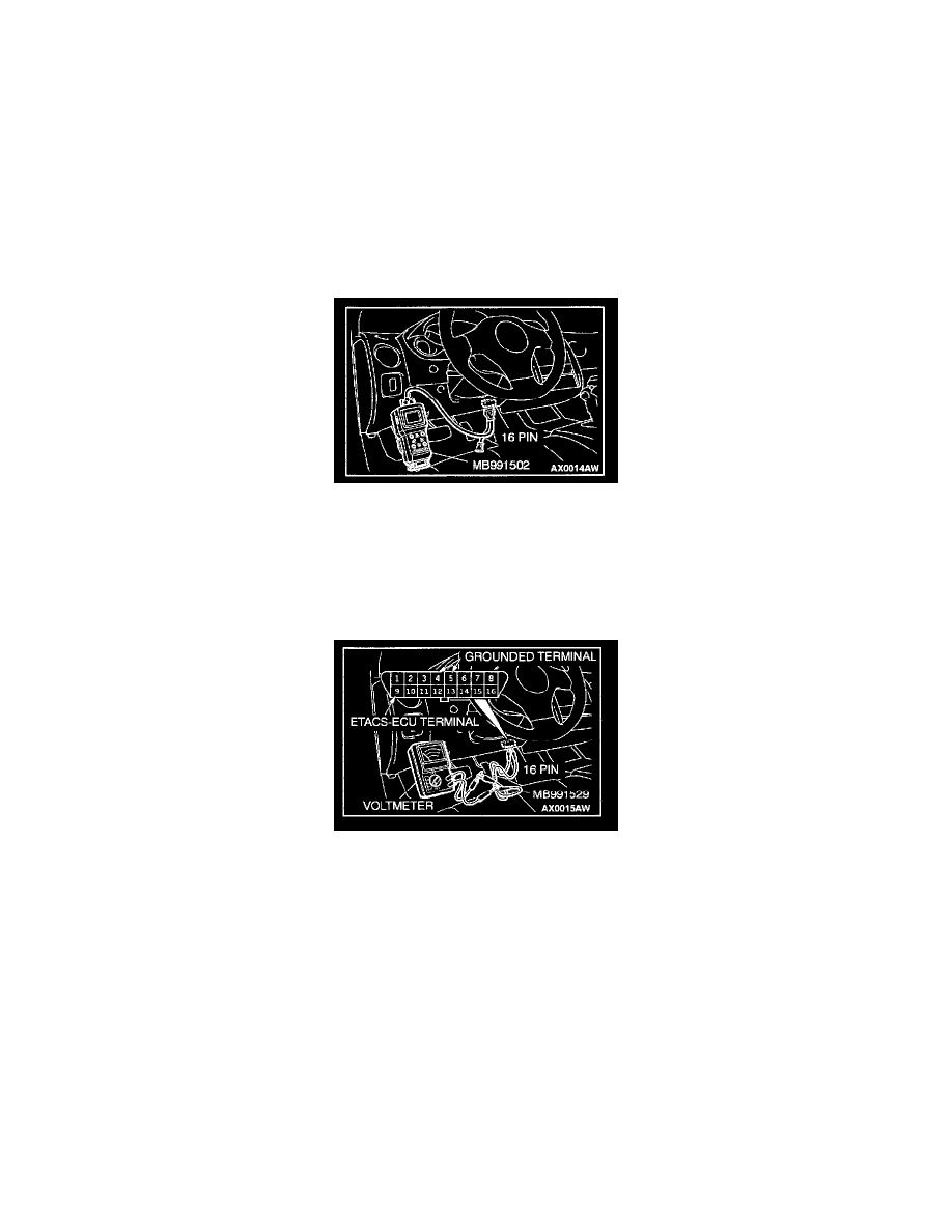
<When using scan tool MB991502>
CAUTION: To prevent damage to scan tool MB991502, always turn the ignition switch to "LOCK" (OFF) position before connecting or disconnecting
scan tool MB991502.
1. Connect scan tool MB991502 to the data link connector.
2. Check that the tone alarm of scan tool MB991502 sounds when the input signal enters.
<When using a voltmeter>
1. Use special tool MB991529 to connect a voltmeter between ground terminal 4 or 5 and ETACS-ECU terminal 9 of the data link connector.
2. Check that the voltmeter indicator deflects once when the input signal enters.
If one of the input signal checks above shows a defect, check the relevant input signal circuit.
If none of the input signal checks shows a defect, replace the ETACS-ECU.
The dome light dimming function should work normally.
Inspection Procedure N-1