
Eclipse RS L4-2350cc 2.4L SOHC MFI (2002)
1. Connect scan tool MB991502 to the data link connector.
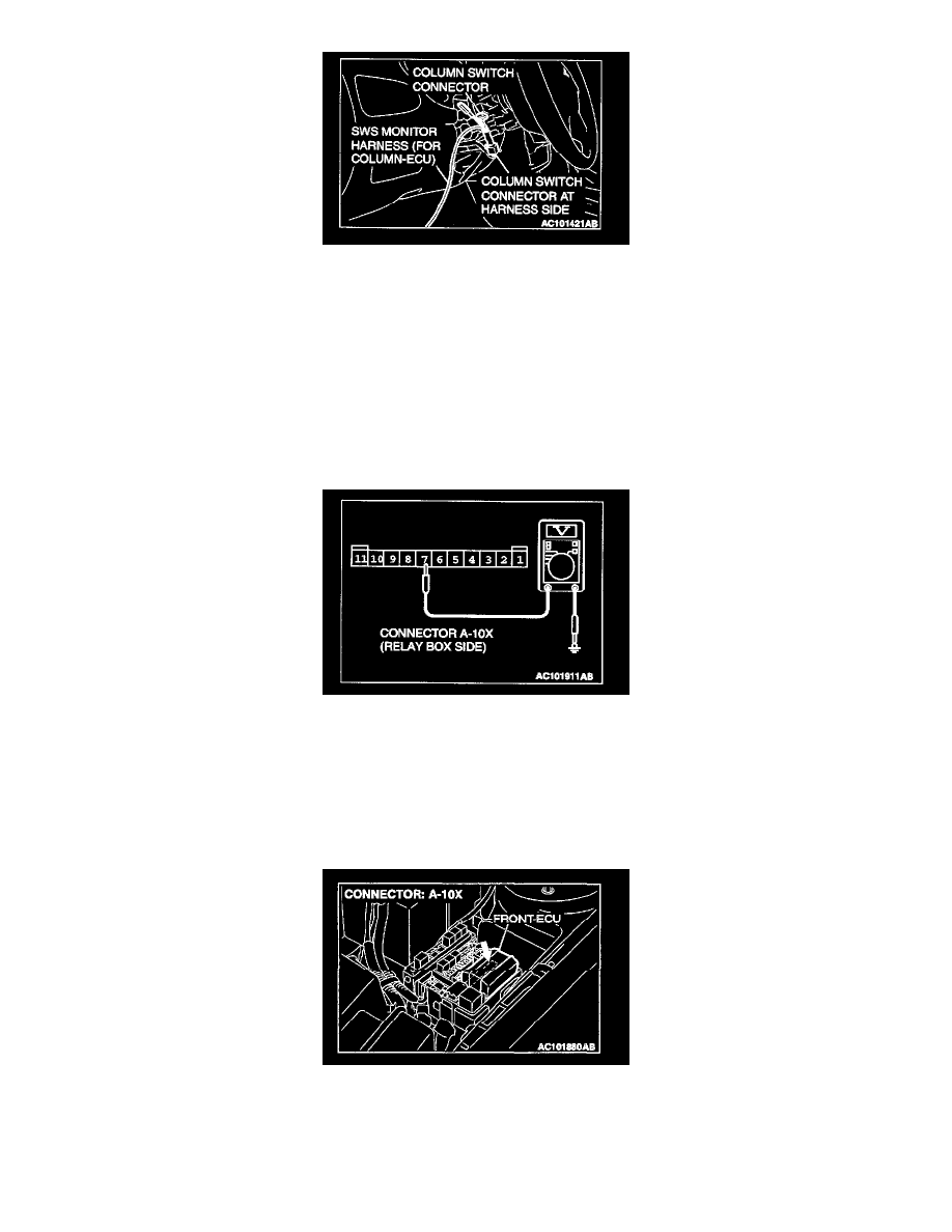
2. Connect SWS monitor kit MB991862 to the column switch connector.
3. When the ignition switch is turned to the "LOCK" (OFF) position, scan tool MB991502 should show "OK" on the "ETACS ECU" menu.
Q: Is "OK" displayed on the "ETACS ECU" menu?
YES: Go to Step 2.
NO: Refer to Inspection Procedure A-3 "Communication with ETACS-ECU is impossible."
STEP 2. Measure at front-ECU connector A-10X in order to check the battery circuit of power supply system to the front-ECU.
1. Disconnect front-ECU connector A-10X, and measure at the relay box side.
2. Measure the voltage between terminal 7 and ground.
-
The measured value should be approximately 12 volts (battery positive voltage).
Q: Does the measured voltage correspond with this range?
YES: Go to Step 5.
NO: Go to Step 3.
STEP 3. Check the front-ECU connector A-10X for damage.
Q: Is front-ECU connector A-10X in good condition?
YES: Go to Step 4.