
Eclipse RS L4-2350cc 2.4L SOHC MFI (2002)
-
Column
CAUTION: To prevent damage to scan tool MB991502, always turn the ignition switch to the "LOCK" (OFF) position before connecting or
disconnecting scan tool MB991502. Also connect SWS monitor kit MB991862 after turning on scan tool MB991502.
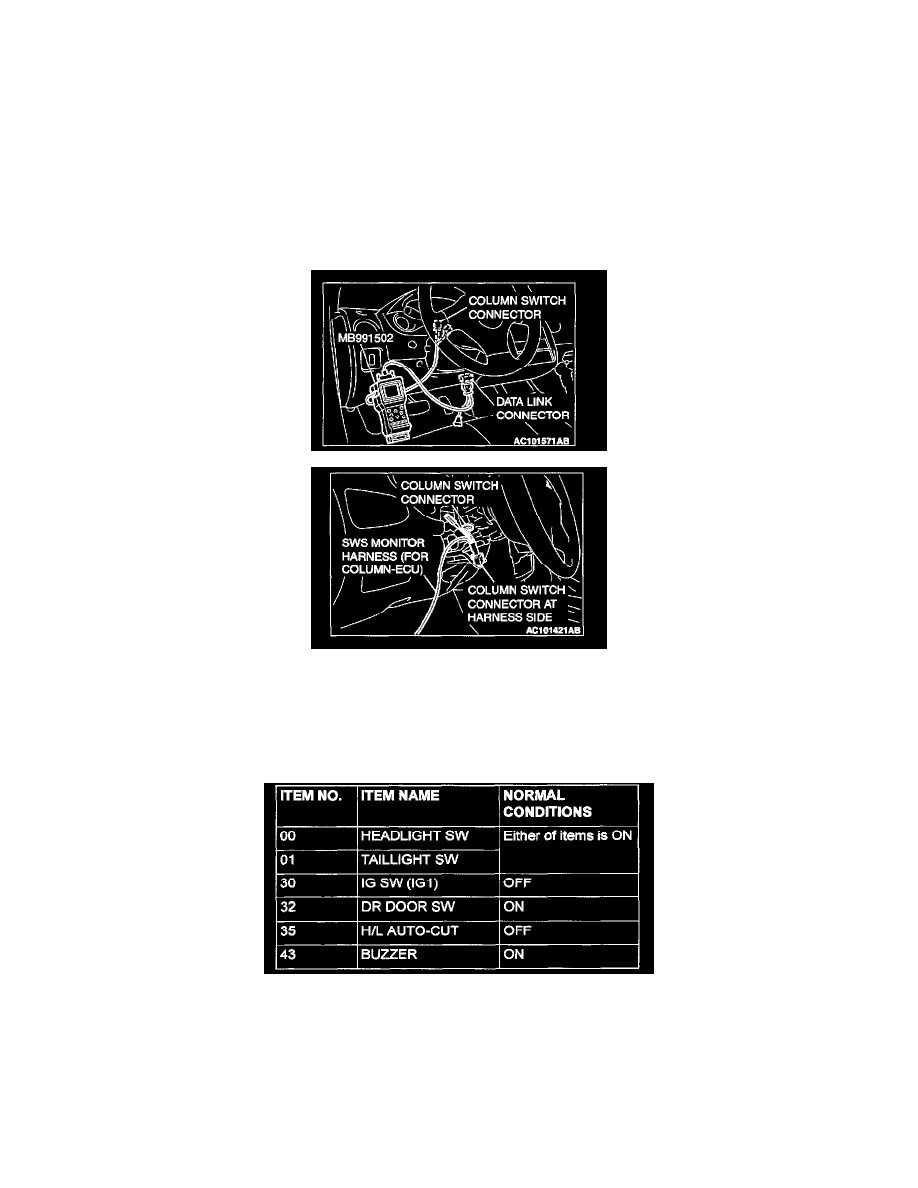
1. Connect scan tool MB991502 to the data link connector.
2. Connect SWS monitor kit MB991862 to the column switch connector.
3. When the ignition switch is turned to the "LOCK" (OFF) position, scan tool MB991502 should show "OK" on the "ECU CHECK" menu.
Q: Are "OK" displayed on the "ETACS ECU" and "COLUMN ECU" menus? "OK" are displayed for all the items : Go to Step 2.
"NG" is displayed on the "ETACS ECU" menu : Refer to Inspection Procedure A-3 "Communication with ETACS-ECU is impossible."
"NG" is displayed on the "COLUMN ECU" menu : Refer to Inspection Procedure A-2 "Communication with column switch (column-ECU) is
impossible."
STEP 2. Check the input signal by using service data of the SWS monitor.
Check the input signals from the following switches:
-
Ignition switch: OFF (key removed)
-
Lighting switch: TAIL or HEAD
-
Driver's door: open
Select "BUZZER-LGT MONI. ALRM" (FUNCTION DIAG.), and check that normal conditions are displayed on the items described in the table.
Q: Does the scan tool display "HEADLIGHT SW", "TAIL LIGHT SW", "IG SW IG1", "DR DOOR SW", "H/L AUTO-CUT" and "BUZZER" as
normal condition?
YES: Replace the ETACS-ECU. The light reminder tone alarm function should work normally.
NO:
-
The scan tool does not show the respective normal condition for item "HEADLIGHT SW." Refer to Inspection Procedure O-8 "ETACS-ECU