
Eclipse RS L4-2350cc 2.4L SOHC MFI (2002)
STEP 2. Check the input signal by using service data of the SWS monitor.
Check the input signals from the following switches:
-
Ignition switch: ON
-
Lighting switch: HEAD
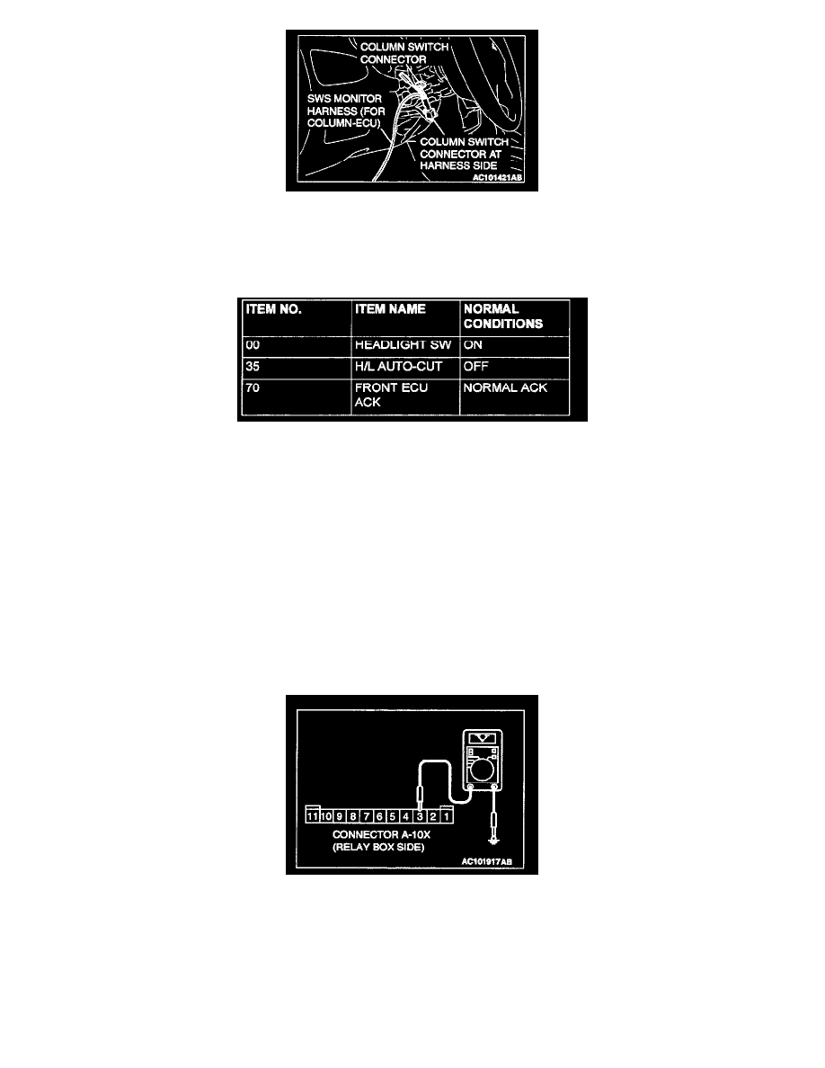
Select "LIGHTING - HEADLIGHT LO" (FUNCTION DIAG.), and check that normal conditions are displayed on the items described in the table.
Q: Does the scan tool display the items "HEADLIGHT SW", "H/L AUTO-CUT" and "FRONT ECU ACK" as normal condition?
YES: Go to Step 3.
NO:
-
The scan tool does not show the respective normal condition for item "HEADLIGHT SW." Refer to Inspection Procedure O-7 "ETACS-ECU
does not receive a signal from the headlight switch."
-
The scan tool does not show the respective normal condition for item "H/L AUTO-CUT." Refer to Inspection Procedure J-9 "Headlight automatic
shutdown function does not work normally."
-
The scan tool does not show the respective normal condition for item "FRONT ECU SW." Replace the ECU. Check that the headlights
(low-beam) illuminate normally.
STEP 3. Measure at front-ECU connector A-10X in order to check the battery circuit of power supply system to the front-ECU.
1. Disconnect front-ECU connector A-10X, and measure at the relay box side.
2. Measure the voltage between terminal 3 and ground.
-
The measured value should be approximately 12 volts (battery positive voltage).
Q: Does the measured voltage correspond with this range?
YES: Replace the front-ECU. Check that the headlights (low-beam) illuminate normally.
NO: Go to Step 4.