
Eclipse Spyder GT V6-3.0L SOHC (2002)
3. Install the bulb to the combination meter, and then measure the resistance value between connector C-41 terminal 52 and connector C-42 terminal
27. The measured resistance value should be roughly the same as the value measured in Step 2..
Q: Are these two resistance values extremely different?
YES: Repair or replace the combination meter (printed circuit board).Check that the seat belt warning light illuminates normally.
NO: (much the same): Go to Step 7.
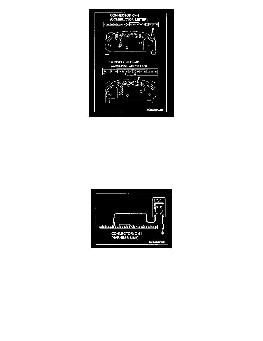
STEP 7. Measure at combination meter connector C-41 in order to check the ignition switch (IG1) line of the power supply to the combination
meter.
1. Disconnect combination meter connector C-41, and measure at the wiring harness side.
2. Turn the ignition switch to the "ON" position.
3. Measure the voltage between terminal 52 and ground.
-
The measured value should be approximately 12 volts (battery positive voltage).
Q: Does the measured voltage correspond with this range?
YES: Go to Step 10.
NO: Go to Step 8.