
Eclipse Spyder GT V6-3.0L SOHC (2002)
STEP 3. Check the wiring harness between ETACS-ECU connector C-119 and the battery.
NOTE: Also check junction block connector C-112 and joint connector C-78 and intermediate connector C-89. If junction block connector C-112 or
joint connector C-78 or intermediate connector C-89 is damaged, repair or replace the connector as described in Harness Connector Inspection.
Q: Is the wiring harness between ETACS-ECU connector C-119 and the battery in good condition?
YES: No action to be taken.
NO: Repair the wiring harness. If the functions or equipment, which are described in "CIRCUIT OPERATION", work normally, the interior light
loaded signal should be normal.
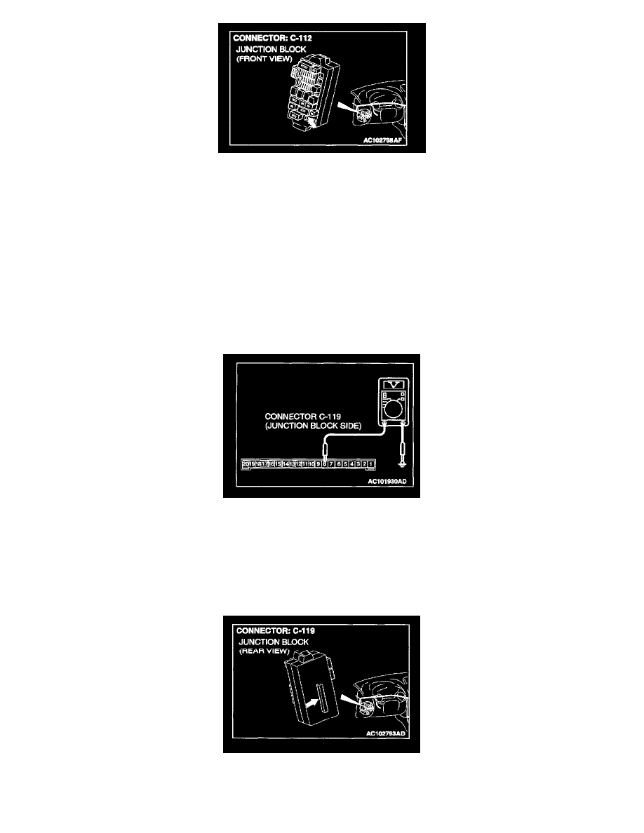
STEP 4. Measure at ETACS-ECU connector C-119 in order to check the ignition switch (IG1) line of the power supply to the ETACS-ECU.
1. Disconnect ETACS-ECU connector C-119, and measure at the junction block side.
2. Turn the ignition switch to the "ON" position.
3. Measure the voltage between terminal 8 and ground.
-
The measured value should be approximately 12 volts (battery positive voltage).
Q: Does the measured voltage correspond with this range?
YES: Go to Step 7.
NO: Go to Step 5.
STEP 5. Check ETACS-ECU connector C-119 for damage.
Q: Is ETACS-ECU connector C-119 in good condition?