
Endeavor V6-3.8L SOHC (2004)
2. Connect the oscilloscope probe to each check harness connector terminal to analyze each cylinder:
-
Terminal No. 151 for the number 1 cylinder.
-
Terminal No. 150 for the number 2 cylinder.
-
Terminal No. 144 for the number 3 cylinder.
-
Terminal No. 148 for the number 4 cylinder.
-
Terminal No. 143 for the number 5 cylinder.
-
Terminal No. 134 for the number 6 cylinder.
Wave Pattern Observation Points
Point: The power transistor control signal (ignition timing) is advanced when the engine speed is increased.
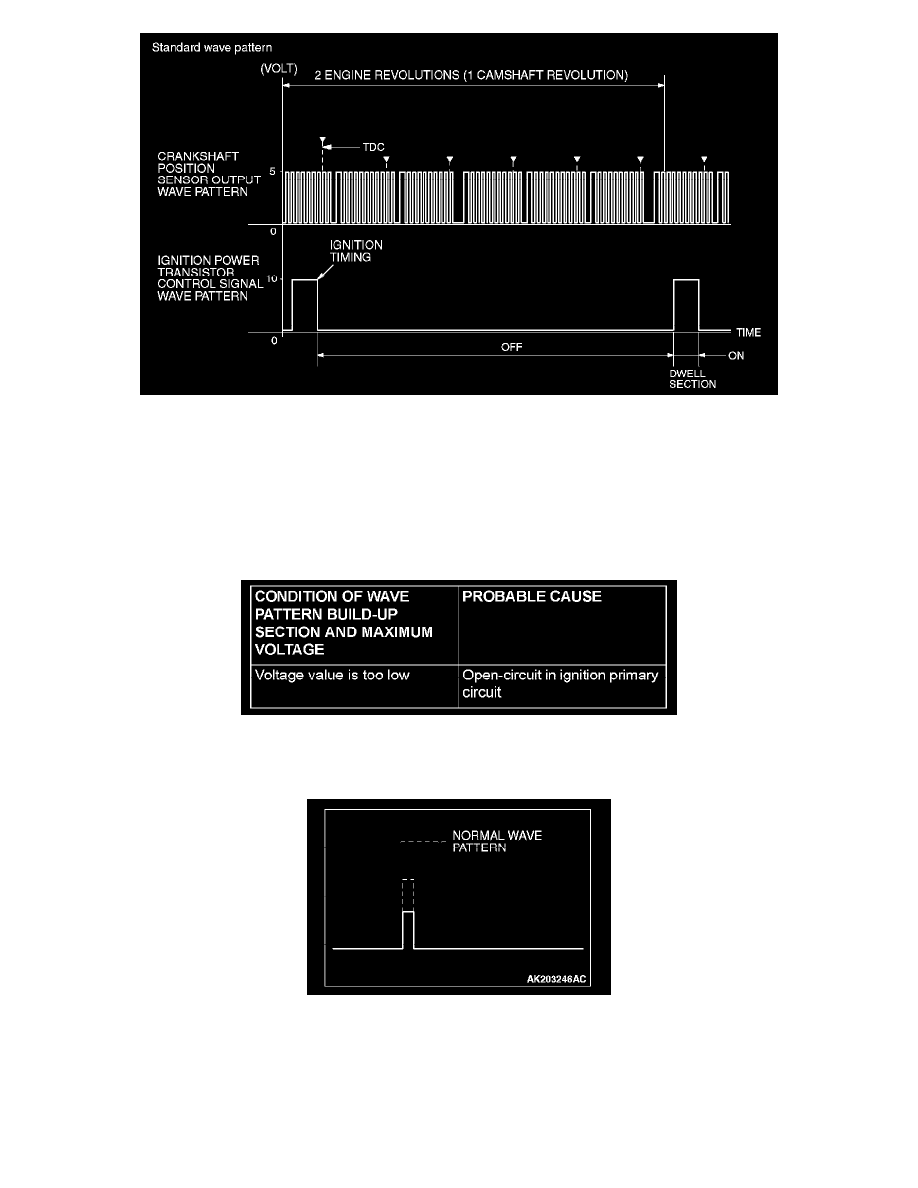
Examples of Abnormal Wave Patterns
Example 1 (Wave pattern during engine cranking)
-
Cause of problem
Open-circuit in ignition primary circuit
-
Wave pattern characteristics
Voltage value is too low.