
Galant L4-1997cc 2.0L DOHC (1990)
Cruise Control Servo: Testing and Inspection
ELECTRICAL TYPE
Continuity Check
Fig. 20 Actuator Check
1.
Disconnect electrical connector.
2.
Measure resistance value of clutch coil, between terminals 1 and 2, Fig. 20. Standard value should read 20 ohms.
Actuator Operation Check
Fig. 21 Actuator Operation Circuit Check
1.
Connect terminal 1, of actuator, through ammeter, to battery positive terminal, Fig. 21.
2.
Connect terminal 2 to battery negative terminal.
3.
Solenoid should emit an audible click and ammeter should measure .5-.7 amps. If not, proceed as follows:
a. If no solenoid noise is heard and ammeter reads 0.0 amps, check for damaged or disconnected clutch coil wiring.
b. If no solenoid sound is heard, but ammeter reads infinite, check for clutch coil short circuit.
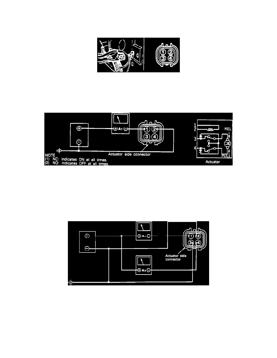
Motor Pull Direction & Limit Switch Operation
Fig. 26 Motor Pull Direction & Limit Switch Operation
1.
Connect ammeters to actuator side connector, Fig. 26.
2.
Current should be cut off when selector is turned in Pull (fully open), direction for full stroke. Ammeter A1 should read .5-.7 amps. Ammeter A2
should read less than .5 amps, when current is on.
3.
If selector moves in Pull direction, ammeter reads .5-.7 amps, but ammeter A2 reads 1 amp or more, check the following:
a. Improper gear backlash, burning between shaft and metal, or insufficient thrust clearance.
4.
If selector does not move, ammeter A1 reads .5-.7 amps and ammeter A2 reads 1 amp or more, check the following:
a. Burned shaft or motor, or foreign material caught between gears.
5.
If selector does not move, ammeter A1 reads .3-.7 amps and ammeter A2 reads 0.0 amps, check the following:
a. Damaged or disconnected internal lead wire or motor wiring, poor contact of limit switch, or open diode.