
Galant L4-2350cc 2.4L SOHC (1985)
8.
Slide the red wire from the modulator extension harness connector under the loosened screw and tighten the screw.
9.
Loosen the next inboard screw 1 turn, slide the remaining white wire under the loosened screw, and tighten the screw
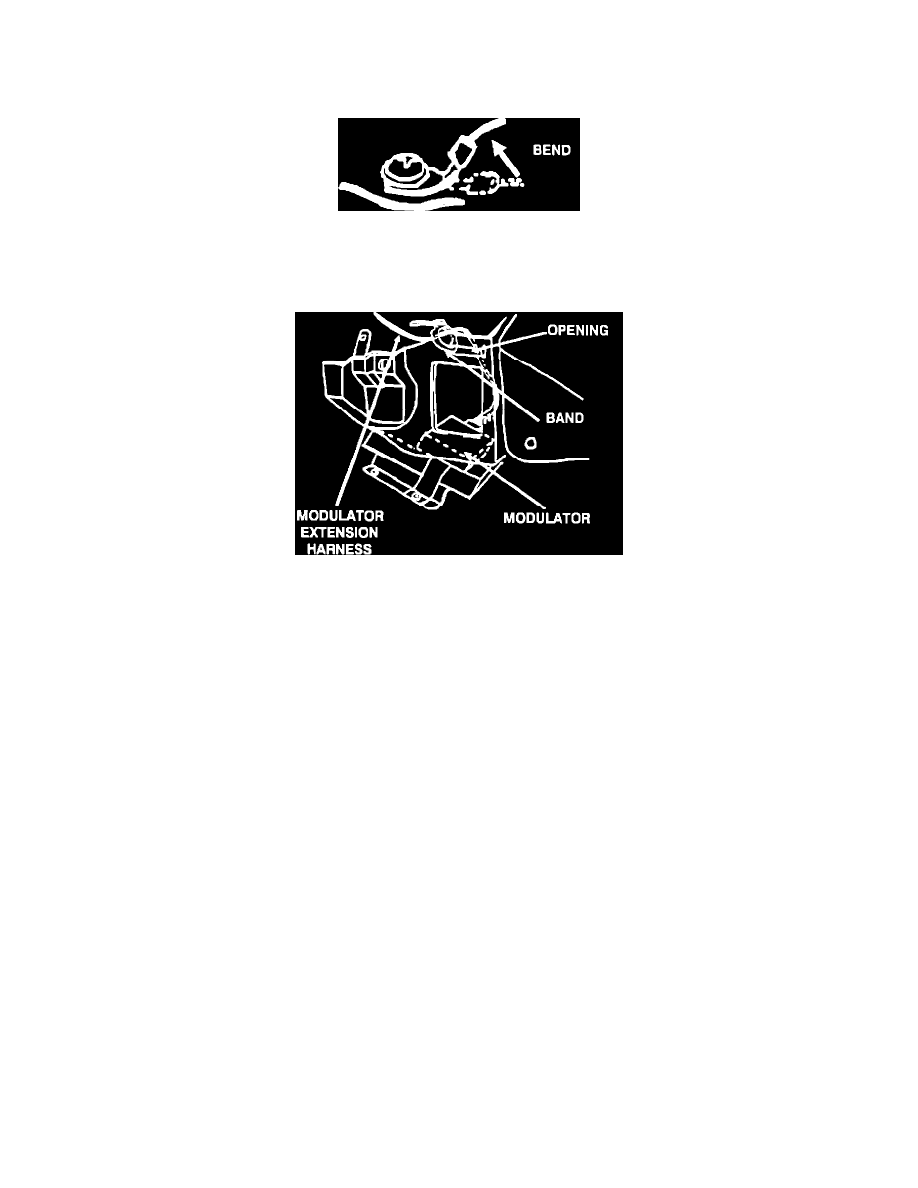
10.
After the connections have been made carefully bend the red wire connector slightly away from the circuit board. Repeat the bending procedure
with the remaining white wire.
DO NOT SCRATCH OR OTHERWISE DAMAGE THE PRINTED CIRCUIT BOARD.
11.
Reinstall the instrument cluster and bezel using the reverse procedure. Use care and verify that the harness extension is clear of the speedometer
cable connector.
12.
Using the supplied band, pass one end through the opening just above the driver's side access hole. Route the new modulator extension harness
between the upper dash and the wire tie. Secure the band and extension harness by passing the free end of the band above the heater access panel.
Tighten the band.
Gently pull any remaining extension harness wire and lay the excess wire above the TCU.
13.
Looking underneath the dash verify that the extension harness wires are not contacting any sharp object and there is no interference with the
accelerator.
14.
Verify that the extension wire is completely hidden from view.
15.
Reinstall the right and left access panels and securing button.
16.
Reinstall the right and left carpeting.
17.
Reconnect the negative battery cable.
18.
Test drive vehicle for proper transmission operation.
19.
Verify instrument operation.