
Galant AWD L4-1997cc 2.0L DOHC Turbo (1991)
Detonation Sensor: Description and Operation
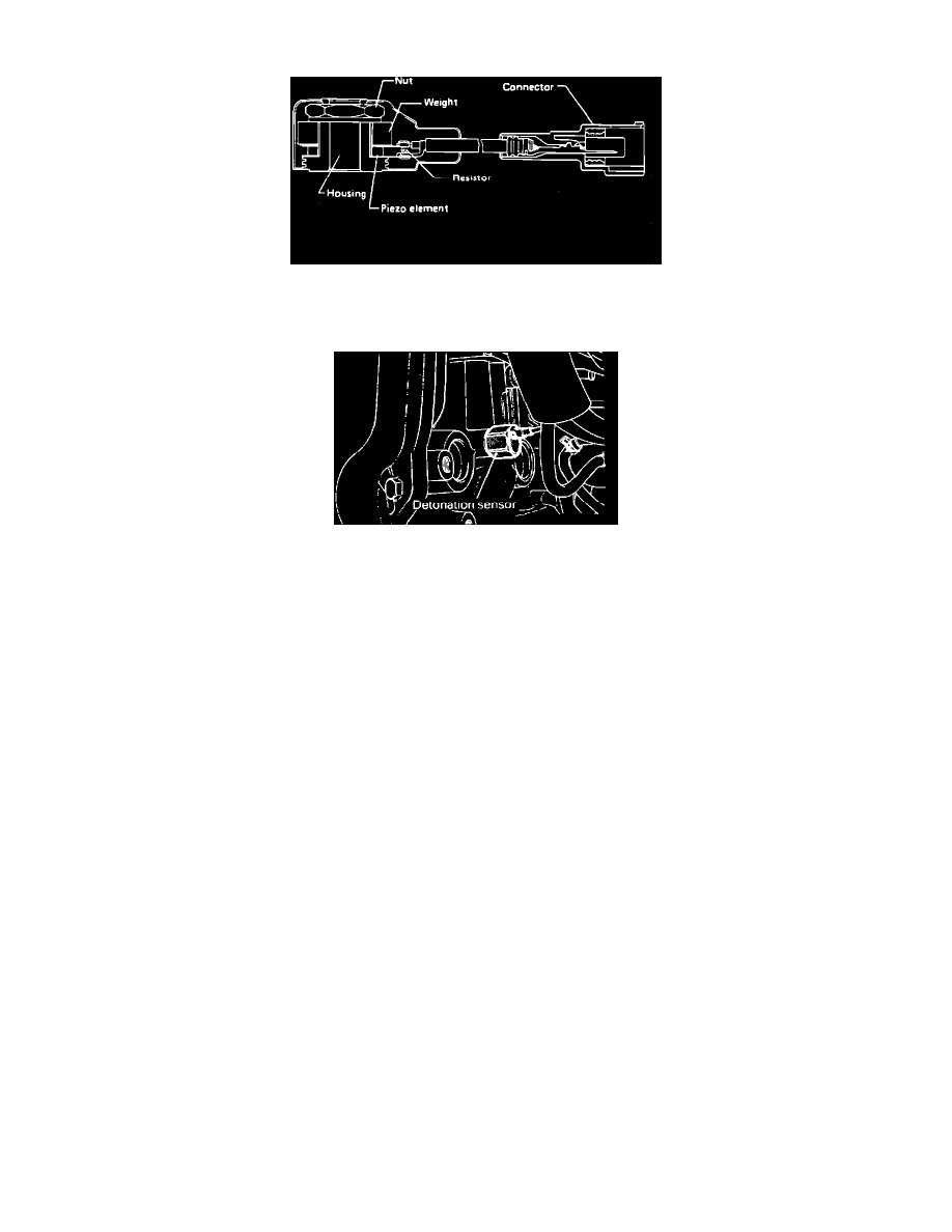
Knock Sensor
The knock sensor is a piezo-electric type which converts knocking vibrations into electric signals.
Knock Sensor
It is installed on the engine block and consists of three elements: Titanium Oxide, Zirconium Oxide and Lead. If engine knocking occurs, the crystal
shakes causing an A/C Voltage to be produced. The magnitude of the input signal is used by the ECU to determine how much spark timing retarding
(maximum of 12° at the crankshaft) is required, and how much turbo boost is needed to reduce the engine knocking. With this system, the ECU controls
ignition timing advance and turbo boost to a point immediately before engine knock occurs. Normally the wastegate solenoid is fully grounded when the
key is on, allowing the maximum boost by bleeding of wastegate operating pressure. However if the sensor is shorted (0 Volts) or the circuit is open (5
Volts), the ECU retards the timing and lowers the maximum boost from 12 PSI to 9 PSI, dependent upon the load and RPM information. When this
happens it controls the wastegate solenoid operation to eliminate knocking three ways:
1. The ECU can disconnect the ground (14 Volts) from the solenoid circuit, causing the solenoid to open and allow manifold pressure to open the
wastegate, thus lowering the boost.
2. The ECU can fully ground the solenoid (0 Volts) until it sees a high load signal (based on input from the air flow sensor). It will then duty cycle
the solenoid from 0 to 14 Volts as long as the high load is present.
3. The ECU may fully ground the solenoid circuit (0 Volts) until a light load signal at high RPM (more than 188 Air Flow Hertz at 4500 RPM) is
found. It will then duty cycle the ground up to 14 Volts for a second or two. This will only happen in neutral and revving the engine or while
shifting gears.