
Galant VR4 AWD L4-1997cc 2.0L DOHC Turbo (1992)
Engine Control Module: Component Tests and General Diagnostics
CONTROL RELAY
Failure of the control relay could interrupt power supply to the fuel pump, injectors and ECU, resulting in start failure.
CAUTION: Use caution when connecting jumper wires to the relay. If the polarity is incorrectly connected, the relay will be damaged.
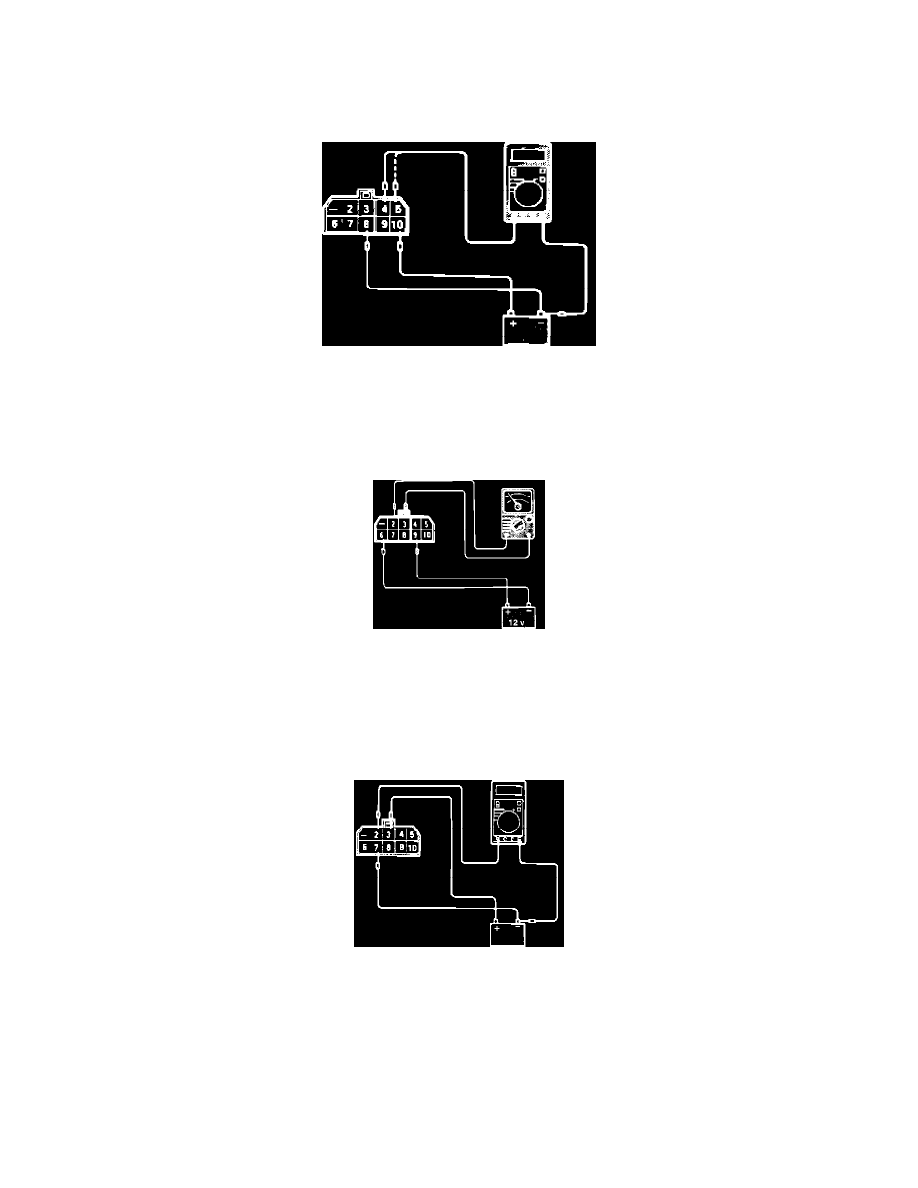
Fig. 1 Relay Test
1. Supply 12 VDC to relay terminals 8 (-) and 10 (+). Using a Voltmeter, check for Voltage between terminals 4 (+) and 8 (-) and between terminals
5 (+) and 8 (-). Refer to Fig. 1.
Voltage: ........................................................................................................................................................................................................ 12 VDC
Fig. 2 Relay Test
2. Supply 12 VDC to relay terminals 6 (-) and 9 (+). Using an Ohmmeter, check for continuity between terminals 2 and 3. Refer to Fig. 2.
Continuity:
-
Should exist when Voltage is supplied.
-
Should NOT exist when Voltage is NOT supplied.
Fig. 3 Relay Test
3. Supply 12 VDC to relay terminals 7 (-) and 3 (+). Using a Voltmeter, check for Voltage between terminals 2 (+) and supply battery ground
terminal. Refer to Fig. 3.
Voltage:
-
12 VDC when terminal 7 is connected.
-
0 VDC when terminal 7 is NOT connected.