
Galant VR4 AWD L4-1997cc 2.0L DOHC Turbo (1992)
Ignition Coil Primary Circuit Test
1. Disconnect the ignition coil connector.
2. Using an Ohm meter, check the resistance between terminals 1 and 3.
Resistance: ...................................................................................................................................................................................... 0.77 - 0.95 Ohms
3. Using an Ohm meter, check the resistance between terminals 2 and 3.
Resistance: ...................................................................................................................................................................................... 0.77 - 0.95 Ohms
Ignition Coil Secondary Circuit Test
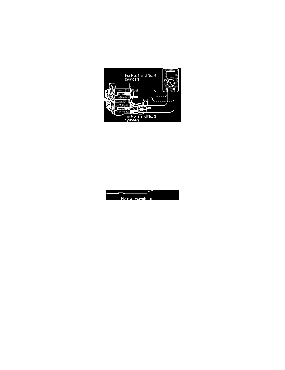
4. Using an Ohm meter, check the resistance between secondary terminals for cylinders No. 1 and No. 4.
Resistance: .................................................................................................................................................................................. 10.3k - 13.9k Ohms
5. Using an Ohm meter, check the resistance between secondary terminals for cylinders No. 2 and No. 3.
Resistance: .................................................................................................................................................................................. 10.3k - 13.9k Ohms
Replace the ignition coil if it fails any of these tests.
Power Transistor Control Signal Scope Pattern
OSCILLOSCOPE TEST
1. Run engine at idle speed.
2. Connect the scope probe to pick-up point #2 (one side at a time) shown in the system schematic diagram and compare each signal to the pattern
shown.
If scope pattern is not as depicted in image, continue with the rest of the test procedures before replacing the assembly.
HARNESS TEST
1. Disconnect the ignition coil connector and turn the key to the ON position.
2. Using a Voltmeter, measure the power supply circuit of the ignition coil between the harness connector terminal 1 and ground and the transistor
harness connector terminal 7 and ground.
Voltage: .............................................................................................................................................................................................. System Voltage
3. Turn the key to the OFF position and disconnect the negative battery cable and ECU connector. Using an Ohmmeter, check for continuity between
the transistor harness connector terminal 4 and ECU harness connector terminal 109.
Continuity: .............................................................................................................................................................................................. Should exist
4. Using an Ohmmeter, check for continuity between the ECU harness connector terminal 109 and ground.
Continuity: ........................................................................................................................................................................................ Should not exist
5. Disconnect the power transistor connector. Using an Ohmmeter, check for continuity between the coil harness connector terminal 1 and the power
transistor harness connector terminal 1.
Continuity: .............................................................................................................................................................................................. Should exist