
Lancer L4-2.4L SOHC (2005)
Valve Clearance: Testing and Inspection
INTAKE AND EXHAUST VALVE CLEARANCE (INSPECT AND ADJUST)
1. Before checks, check that the engine oil, starter and battery are normal. Also, set the vehicle in the following condition:
^
Engine coolant temperature: 80 - 95°C (176 - 203°F)
^
Lights and all accessories: OFF
^
Transaxle: Neutral (P range on vehicles with A/T)
NOTE: Vehicles for Canada, the headlight, taillight, etc. remain lit even when the lighting switch is in OFF position but this is no problem for
checks and adjustment.
2. Remove all of the ignition coils.
3. Remove the rocker cover.
4. Turn the crankshaft clockwise until the notch on the pulley is lined up with T mark on the timing indicator.
5. Move the rocker arms on the No. 1 and No.4 cylinders up and down by hand to determine which cylinder has its piston at the top dead center on
the compression stroke.
If both intake and exhaust valve rocker arms have a valve lash, the piston in the cylinder corresponding to these rocker arms is at the top dead
center on the compression stroke.
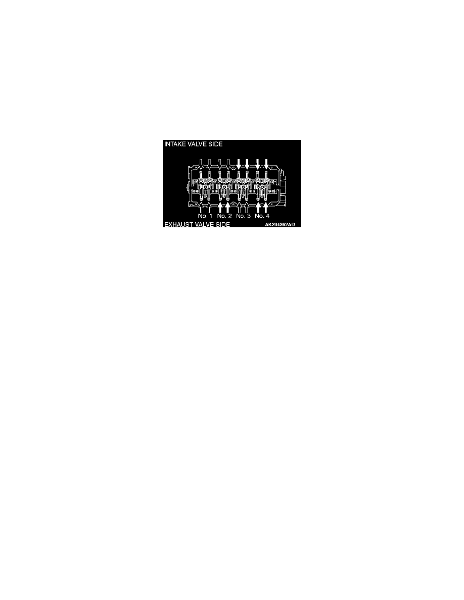
6. Valve clearance inspection and adjustment can be performed on rocker arms indicated by white arrow mark when the No.1 cylinder piston is at the
top dead center on the compression stroke, and on rocker arms indicated by black arrow mark when the No.4 cylinder piston is at the top dead
center on the compression stroke.
7. Measure the valve clearance.
If the valve clearance is not as specified, loosen the rocker arm lock nut and adjust the clearance using a thickness gauge while turning the
adjusting screw.
Standard value (hot engine):
Intake valve: 0.20 mm (0.008 inch)
Exhaust valve: 0.30 mm (0.012 inch)
8. While holding the adjusting screw with a screwdriver to prevent it from turning, tighten the lock nut to the specified torque.
Tightening torque: 9 ± 1 Nm (80 ± 9 inch lbs.)
9. Turn the crankshaft through 360 degree angle to line up the notch on the crankshaft pulley with the T mark on the timing indicator.
10. Repeat steps 7 and 8 on other valves for clearance adjustment.
11. Install the rocker cover.
12. Install the ignition coils.