
Lancer L4-2.4L SOHC (2005)
TECHNICAL DESCRIPTION (COMMENT)
The SWS monitor kit may be connected improperly.
TROUBLESHOOTING HINTS
-
The SWS monitor body (I/F cartridge) may be defective
-
The SWS monitor harness may be defective
-
The ETACS-ECU may be defective
-
The wiring harness or connectors may have loose, corroded, or damaged terminals, or terminals pushed back in the connector
DIAGNOSIS
Required Special Tools:
-
MB991223: Harness Set
-
MB991958: Scan Tool (MUT-III Sub Assembly)
-
MB991824: Vehicle Communication Interface (V.C.I.)
-
MB991827: MUT-III USB Cable
-
MB991911: MUT-III Main Harness B
-
MB991813: SWS Monitor Kit
-
MB991806: SWS Monitor Cartridge
-
MB991812: SWS Monitor Harness (For Column-ECU)
-
MB991922: Probe Harness
STEP 1. Verify SWS monitor kit MB991813 for proper connection.
Q: Is SWS monitor kit MB991813 connected with the column switch properly?
YES: Go to Step 2.
NO: Connect SWS monitor kit MB991813 to the column switch securely.
STEP 2. Verify the power supply circuit to the ETACS-ECU.
Q: Does the system communicate with scan tool MB991958 when the ignition switch is turned to the "ON" position?
YES: Go to Step 3.
NO: Refer to Inspection Procedure A-3 "Communication with the ETACS-ECU is not possible."
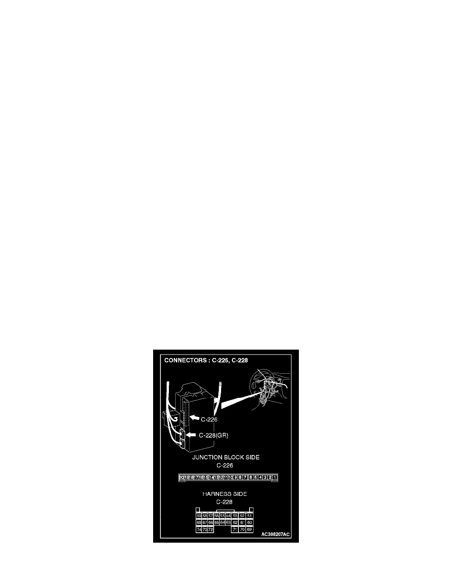
STEP 3. Check ETACS-ECU connector C-226 and C-228 for loose, corroded or damaged terminals, or terminals pushed back in the connector.