
Lancer L4-2.4L SOHC (2005)
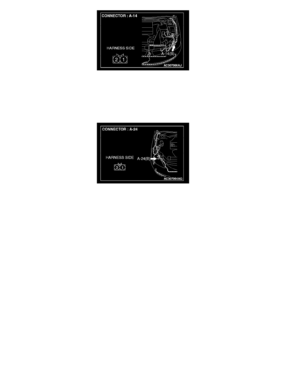
STEP 11. Check the wiring harness between position light (LH) connector A-14 (terminal 2) and front-ECU connector A-10X (terminal 8).
Q: Is the wiring harness between position light (LH) connector A-14 (terminal 2) and front-ECU connector A-10X (terminal 8) in good condition?
YES: No action is necessary and testing is complete.
NO: The wiring harness may be damaged or the connector(s) may have loose, corroded or damaged terminals, or terminals pushed back in the
connector. Repair the wiring harness as necessary. Verify that the position light (LH) illuminates normally.
STEP 12. Check position light (RH) connector A-24 for loose, corroded or damaged terminals, or terminals pushed back in the connector.
Q: Is position light (RH) connector A-24 in good condition?
YES: Go to Step 13.
NO: Repair or replace the damaged component(s). Refer to Harness Connector Inspection. Verify that the position light (RH) illuminates normally.
STEP 13. Check the position light bulb (RH).
1. Remove the position light bulb (RH).
2. Verify that the position light bulb (RH) is not damaged or burned out.
Q: Is the position light bulb (RH) in good condition?
YES: Go to Step 14.
NO: Replace the position light bulb (RH). Verify that the position light (RH) illuminates normally.
STEP 14. Check the ground circuit to the position light (LH). Measure the resistance at position light (LH) connector A-24.