
Lancer L4-2.4L SOHC (2005)
STEP 2. Check the front-ECU connector A-10X for loose, corroded or damaged terminals, or terminals pushed back in the connector.
Q: Is the front-ECU connector A-10X in good condition?
YES: Go to Step 3.
NO: Repair or replace the damaged component(s). Refer to Harness Connector Inspection. The system should communicate with the front-ECU
normally.
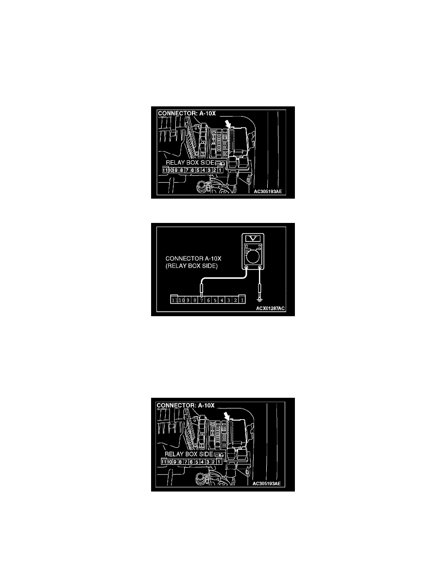
STEP 3. Check the battery power supply circuit to the front-ECU. Measure the voltage at front-ECU connector A-10X.
1. Disconnect front-ECU connector A-10X and measure the voltage available at the relay box side of the connector.
2. Measure the voltage between terminal 7 and ground.
-
The voltage should equal approximately 12 volts (battery positive voltage).
Q: Is the measured voltage approximately 12 volts (battery positive voltage)?
YES: Go to Step 5.
NO: Go to Step 4.
STEP 4. Check the wiring harness between front-ECU connector A-10X (terminal 7) and the battery.
Q: Is the wiring harness between front-ECU connector A-10X (terminal 7) and the battery in good condition?
YES: No action is necessary and testing is complete.
NO: The wiring harness may be damaged or the connector(s) may have loose, corroded or damaged terminals, or terminals pushed back in the